Схемы, предохранители и реле Hyundai HD 65/72/78.
Смотрите также:
Схемы электрооборудования (другой вариант).
Table of contents.
- Power distribution.
- Passenger compartment fuse details.
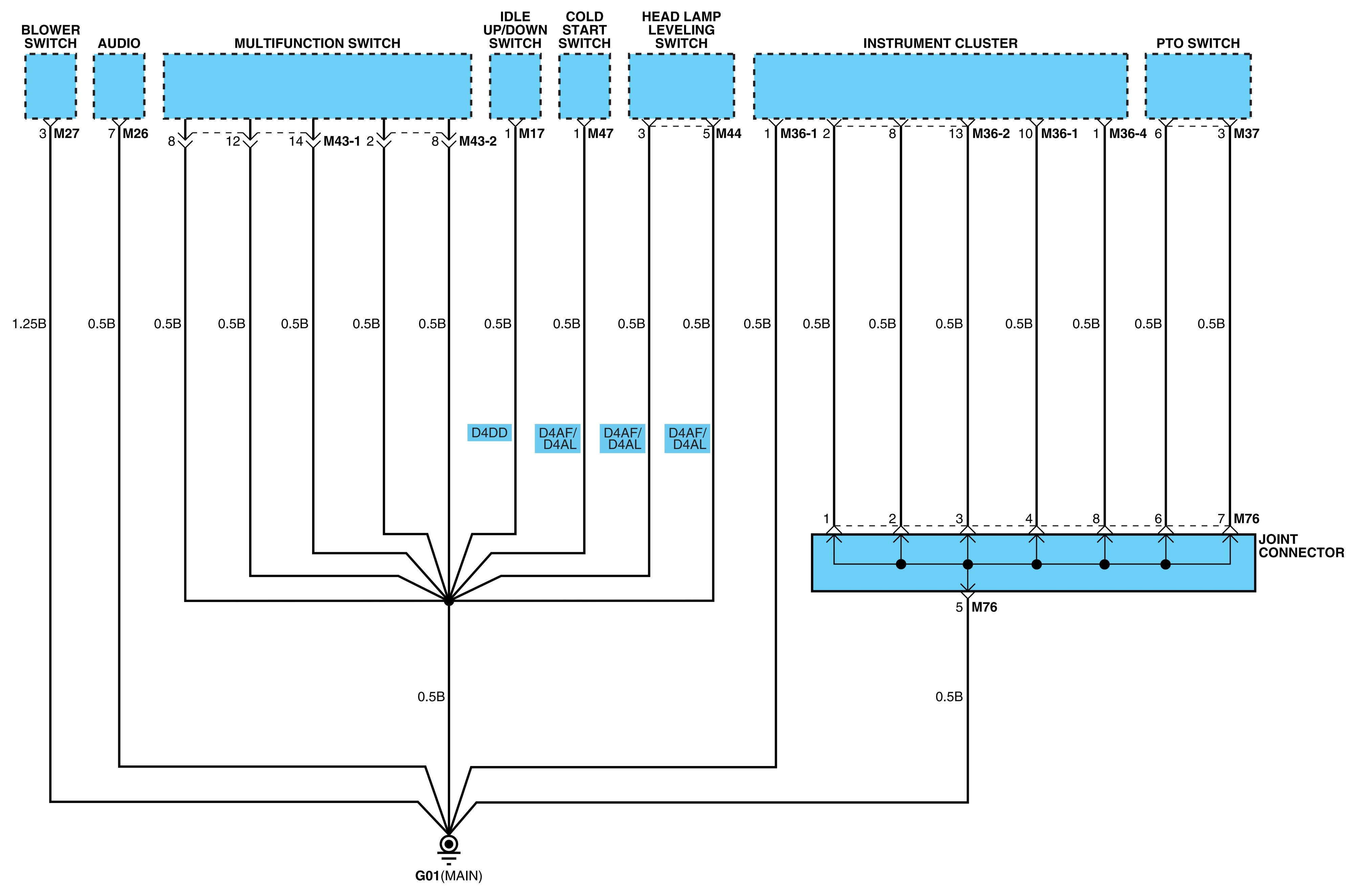
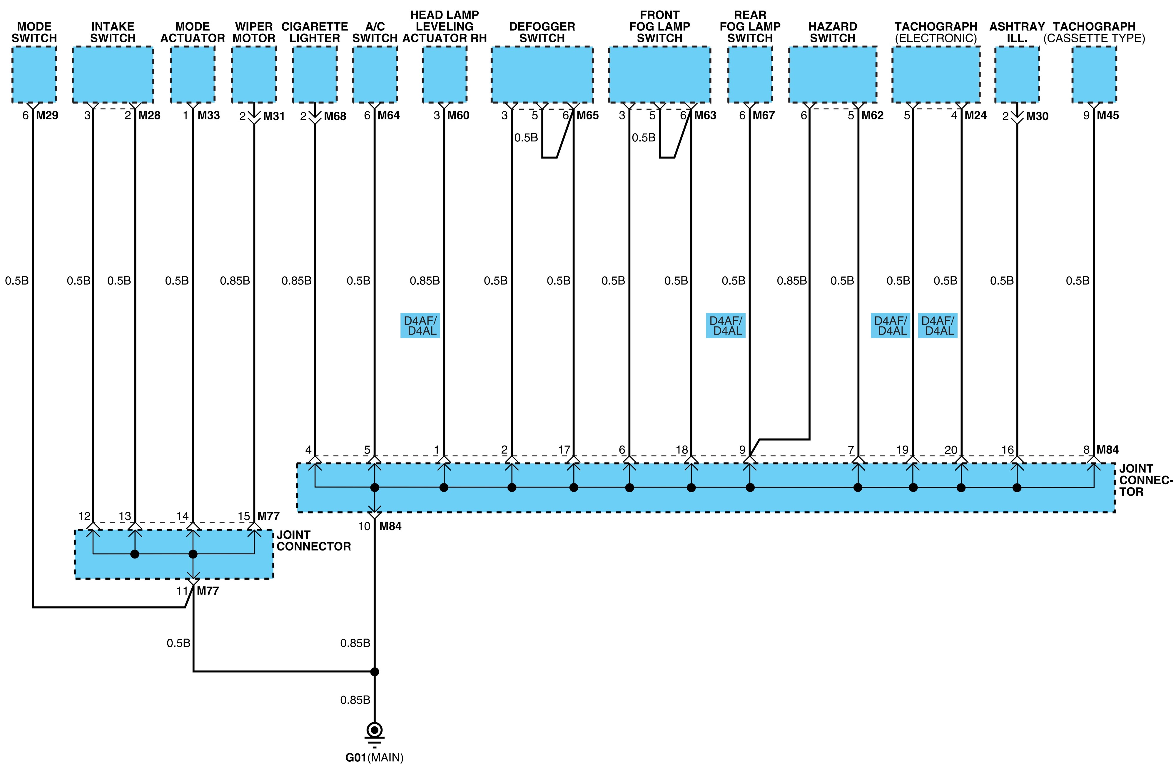
- Ground distribution.
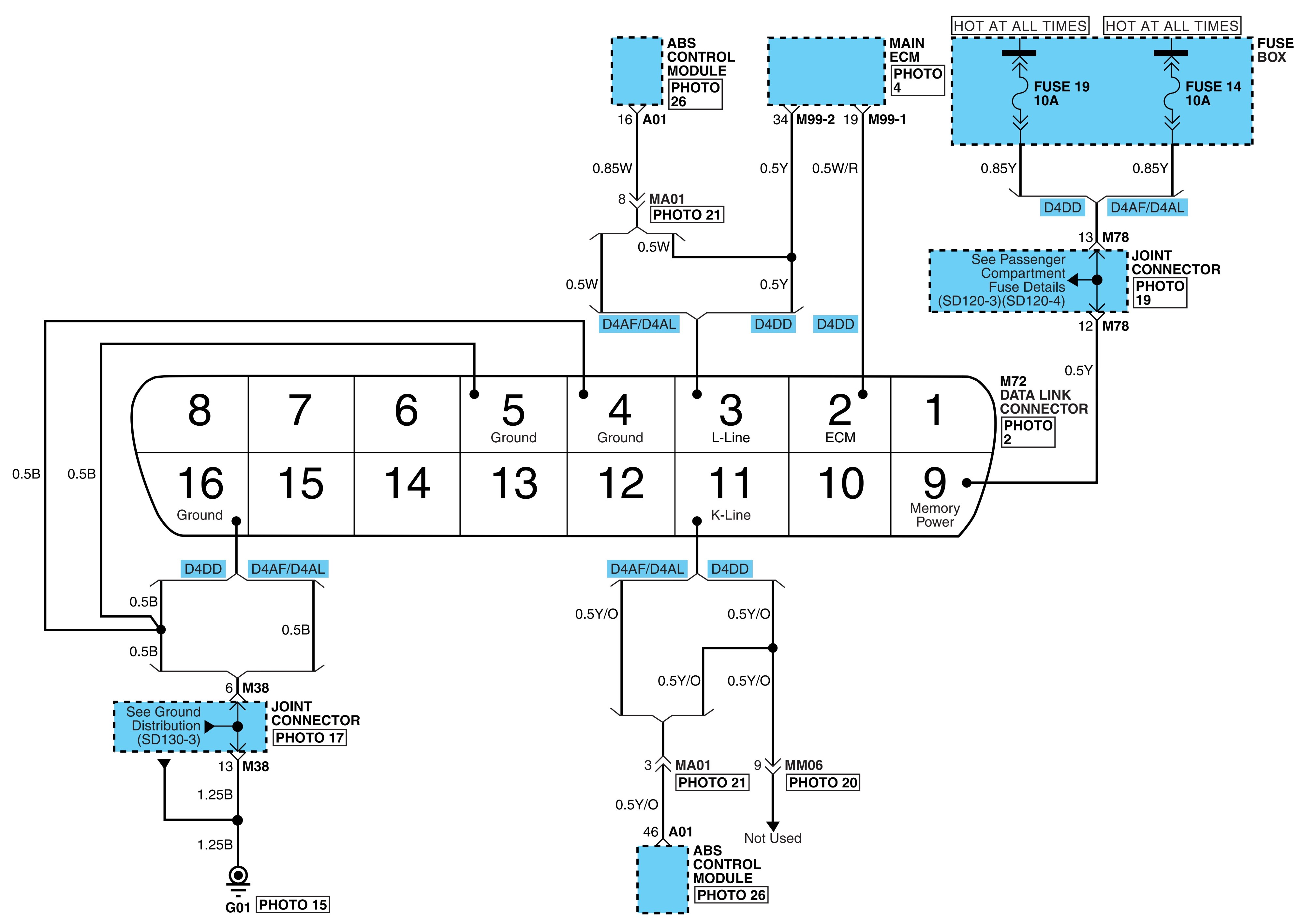
- Data link details.
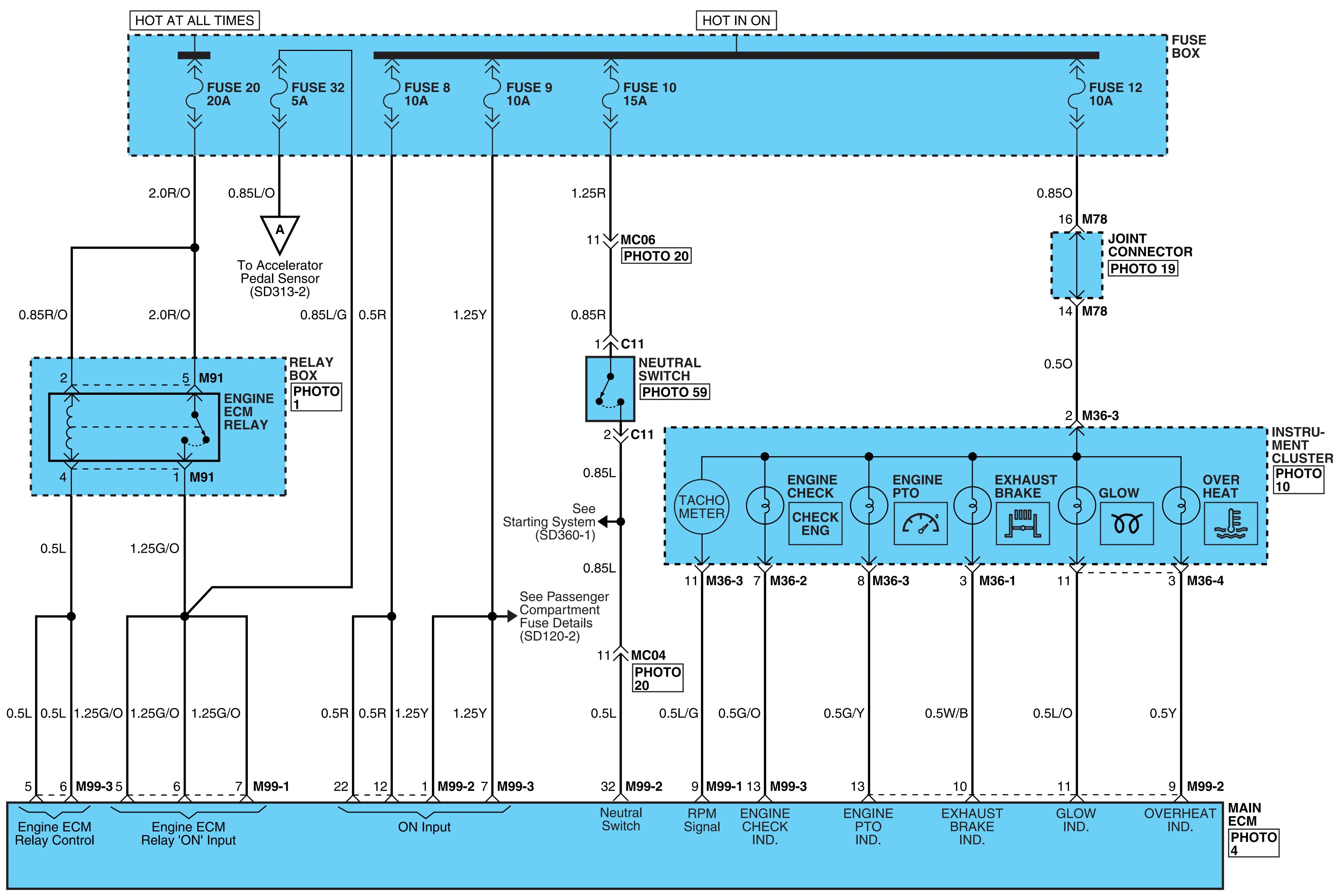
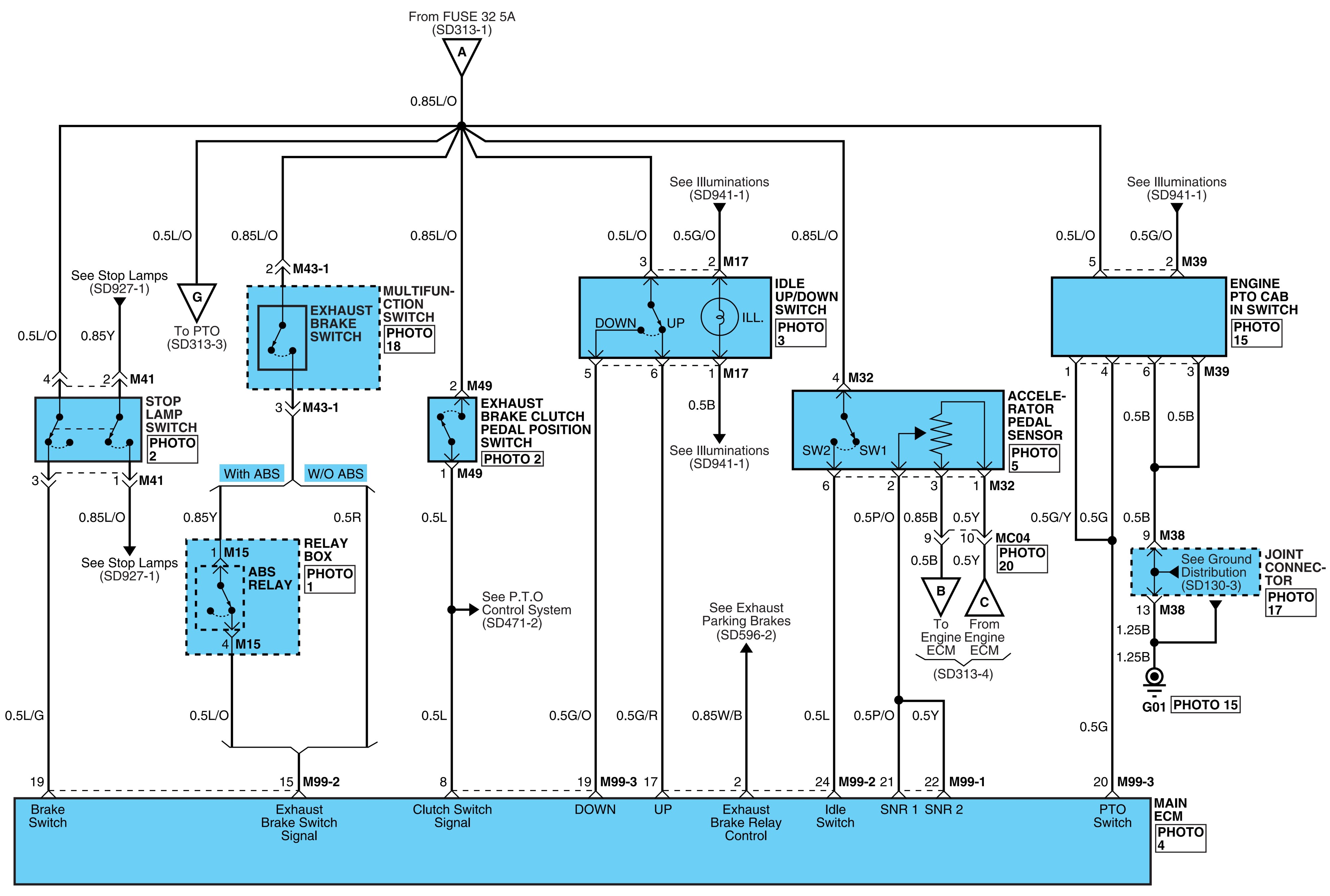
- MFI control system (D4DD).
- Starting system.
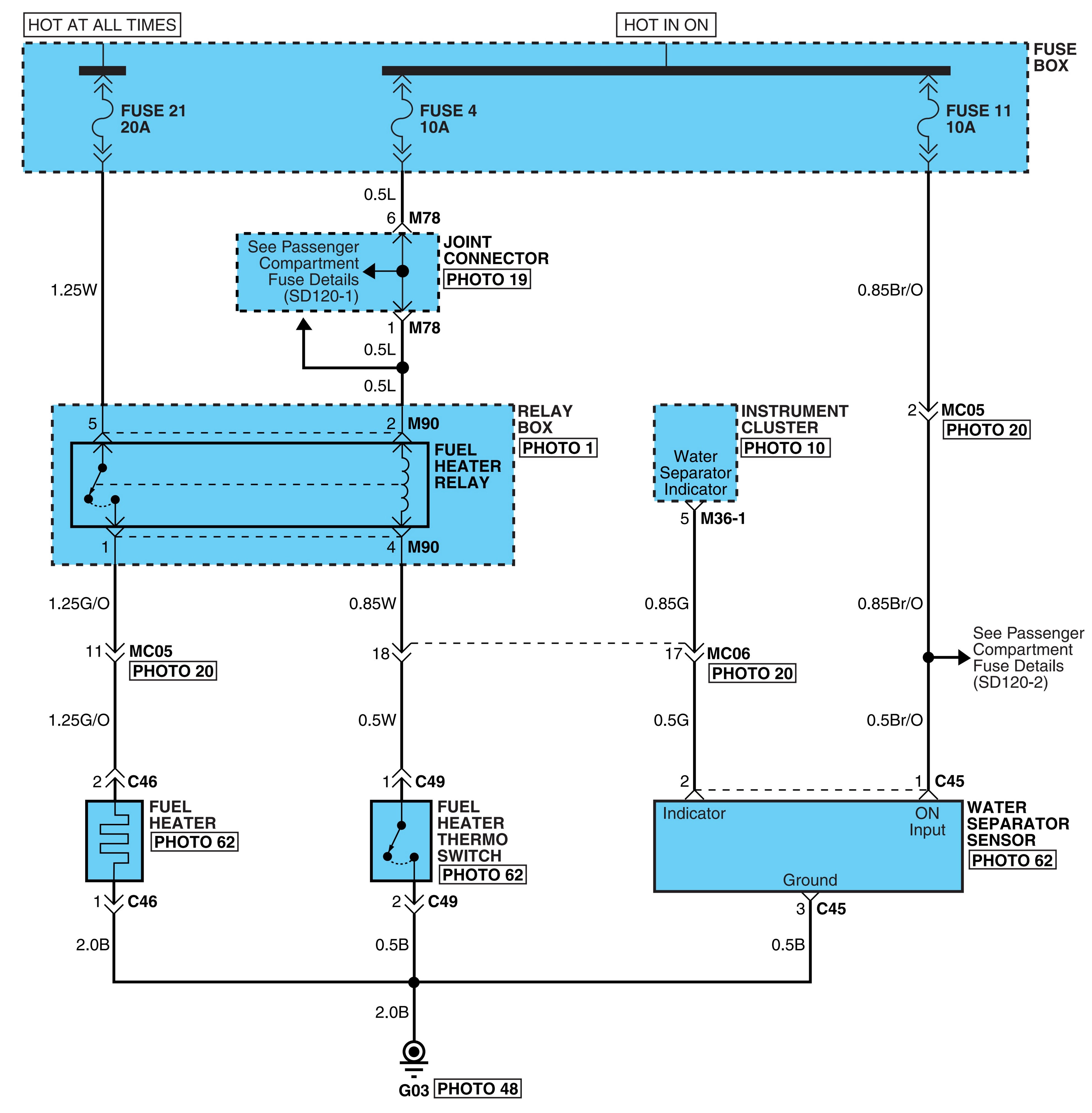
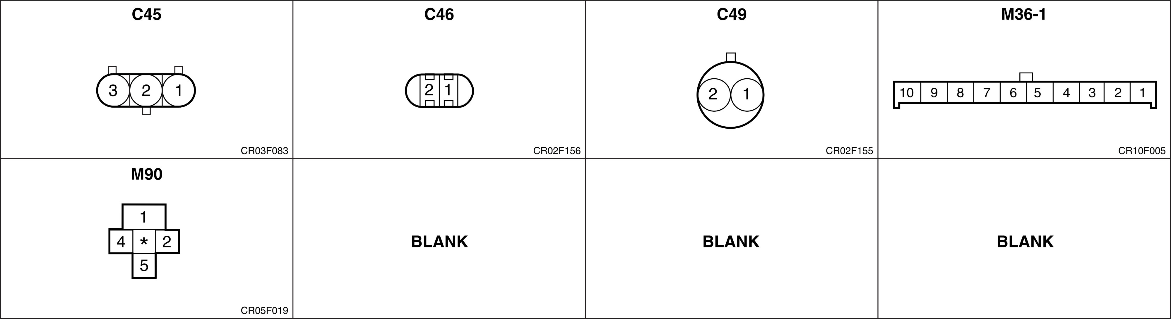
- Fuel filter heating system (D4DD).
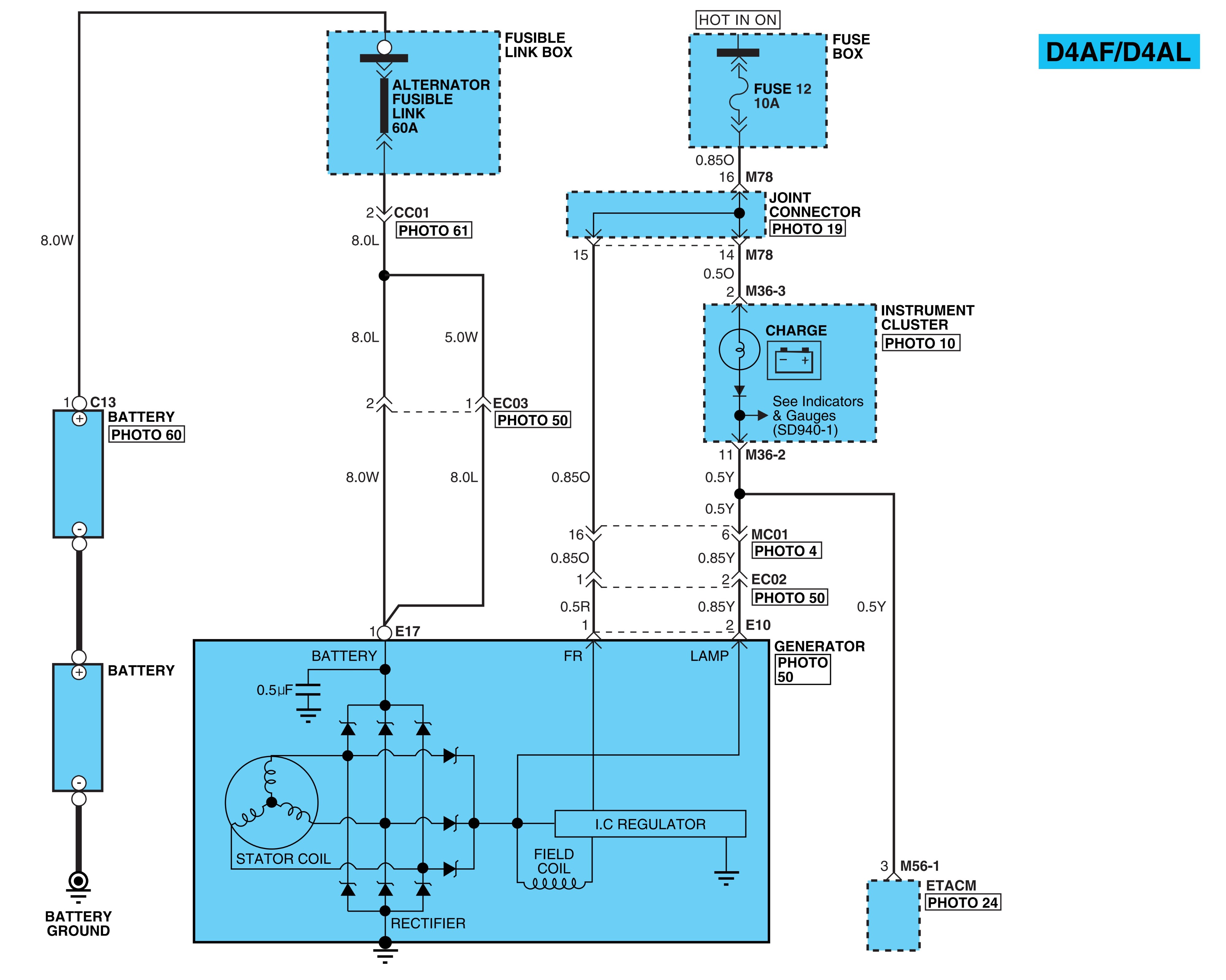
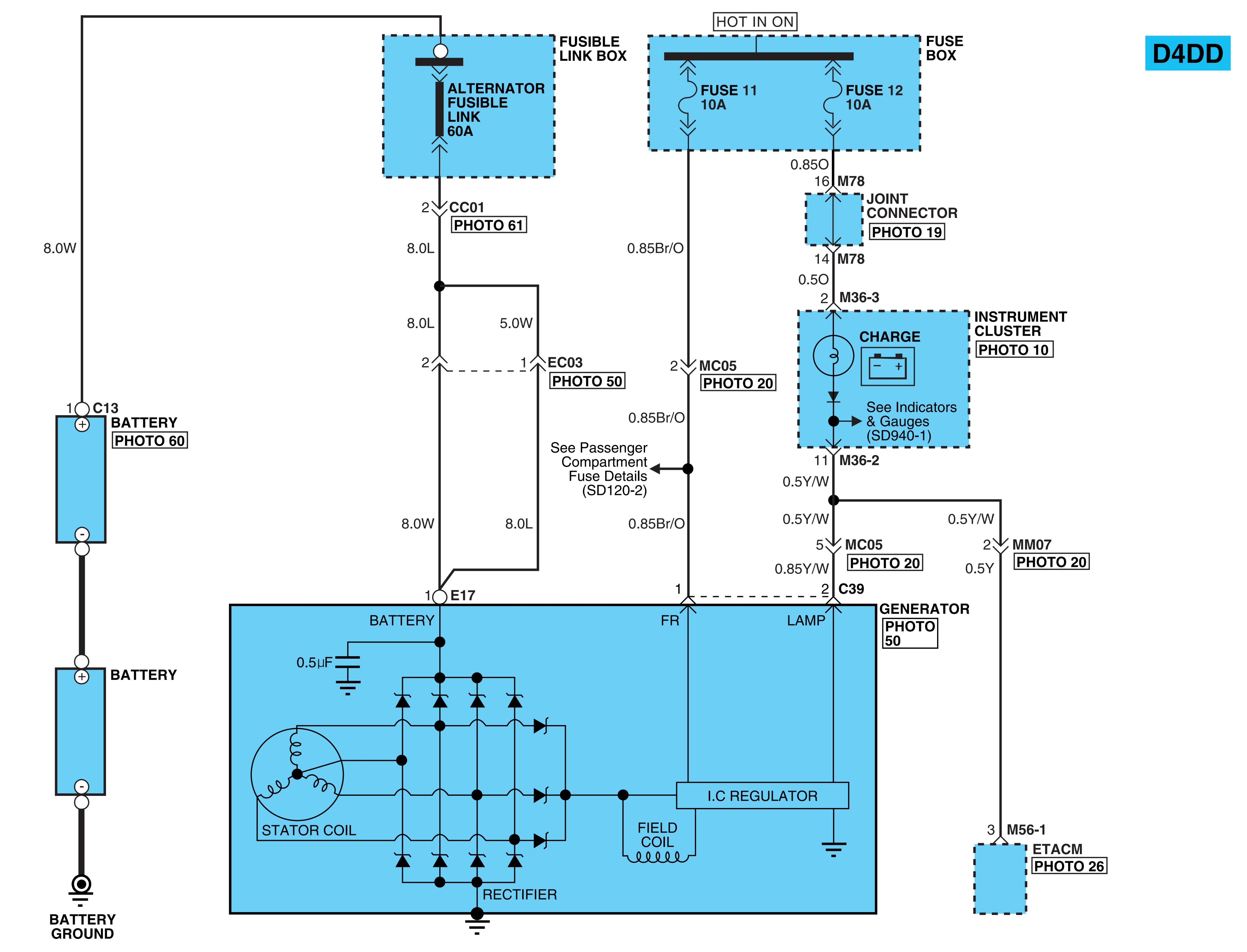
- Charging system.
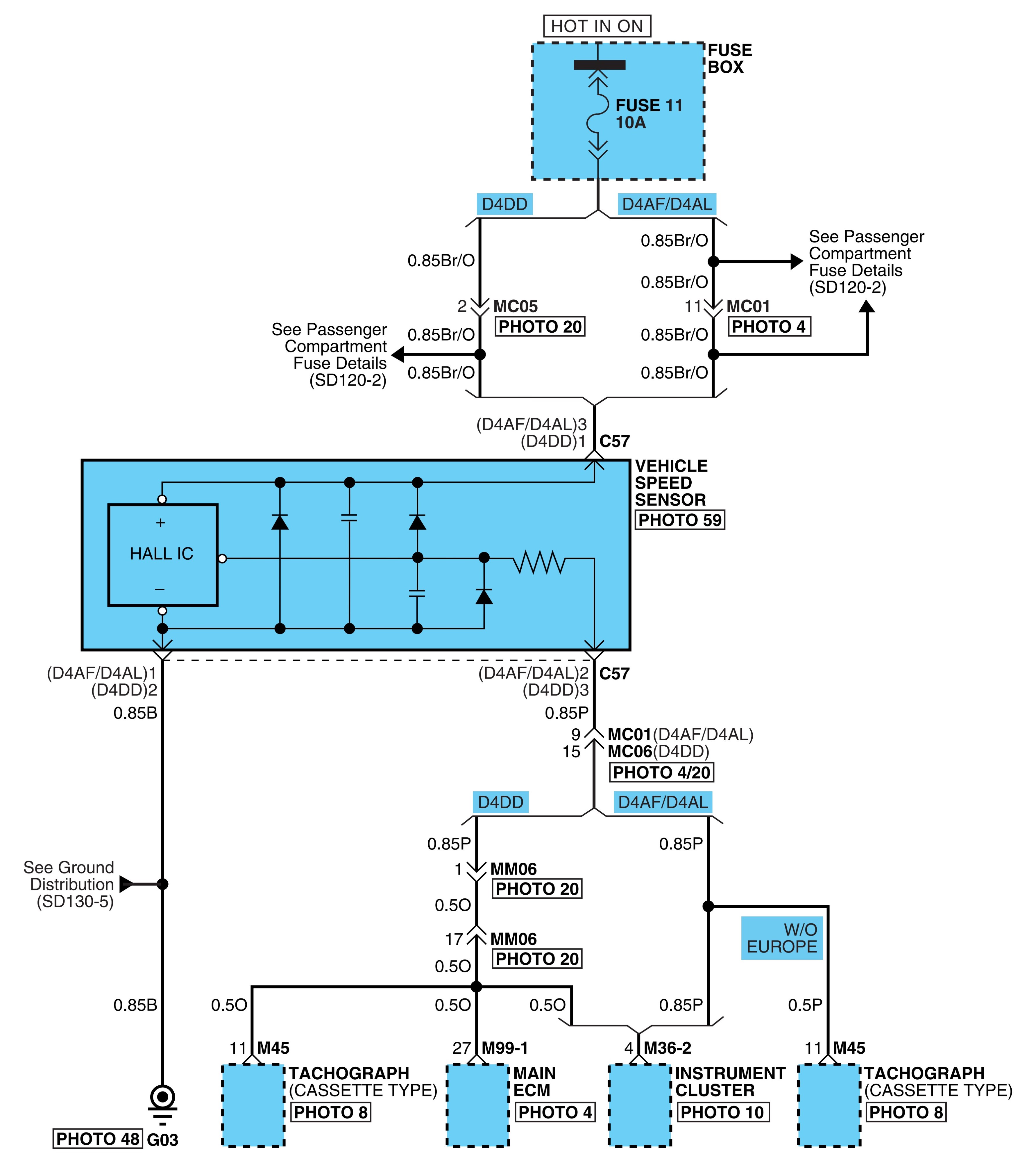
- Vehicle speed sensor system.
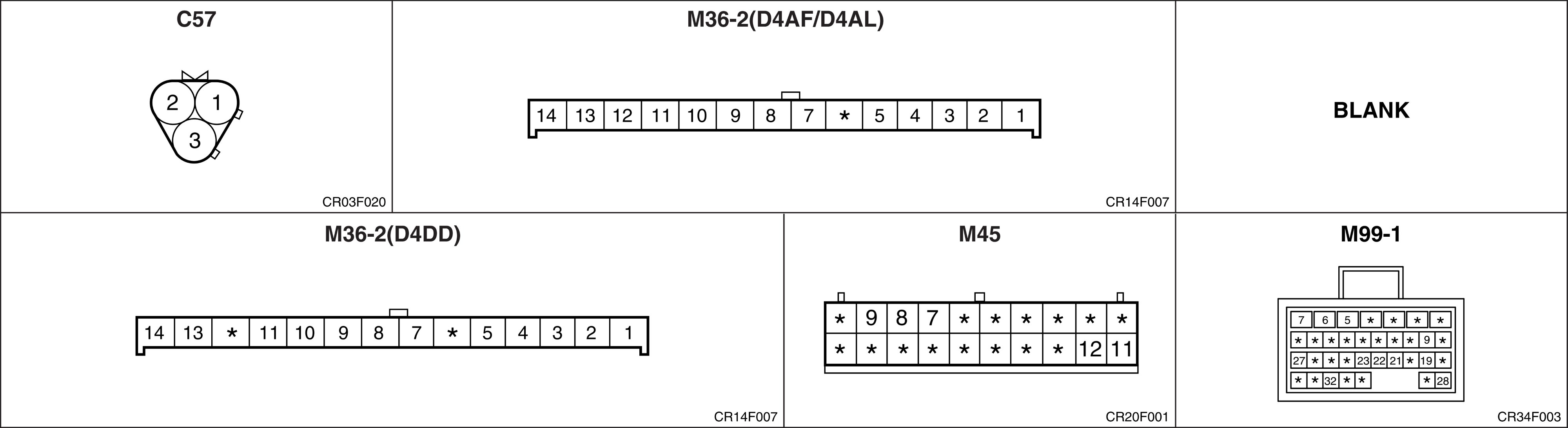
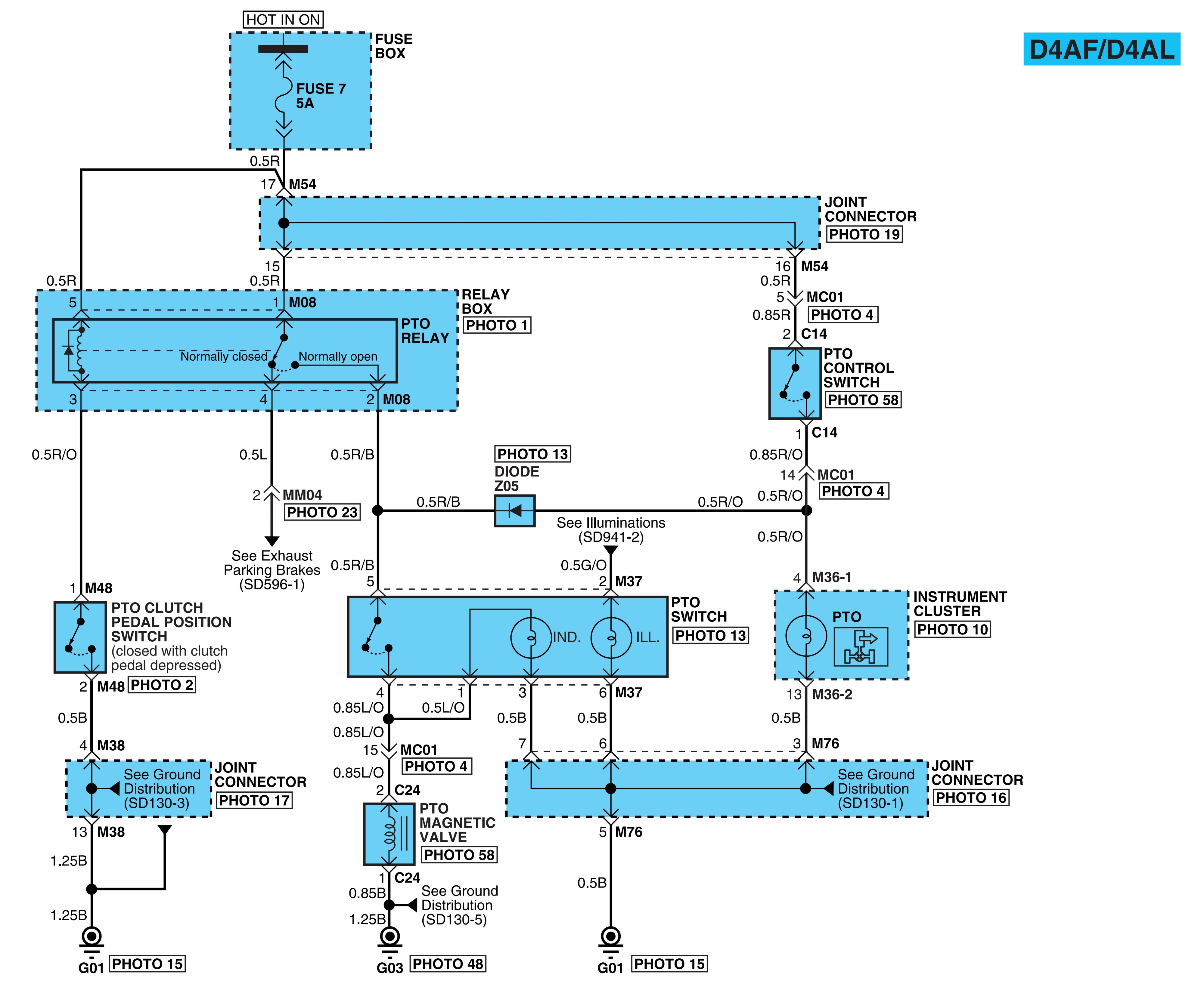
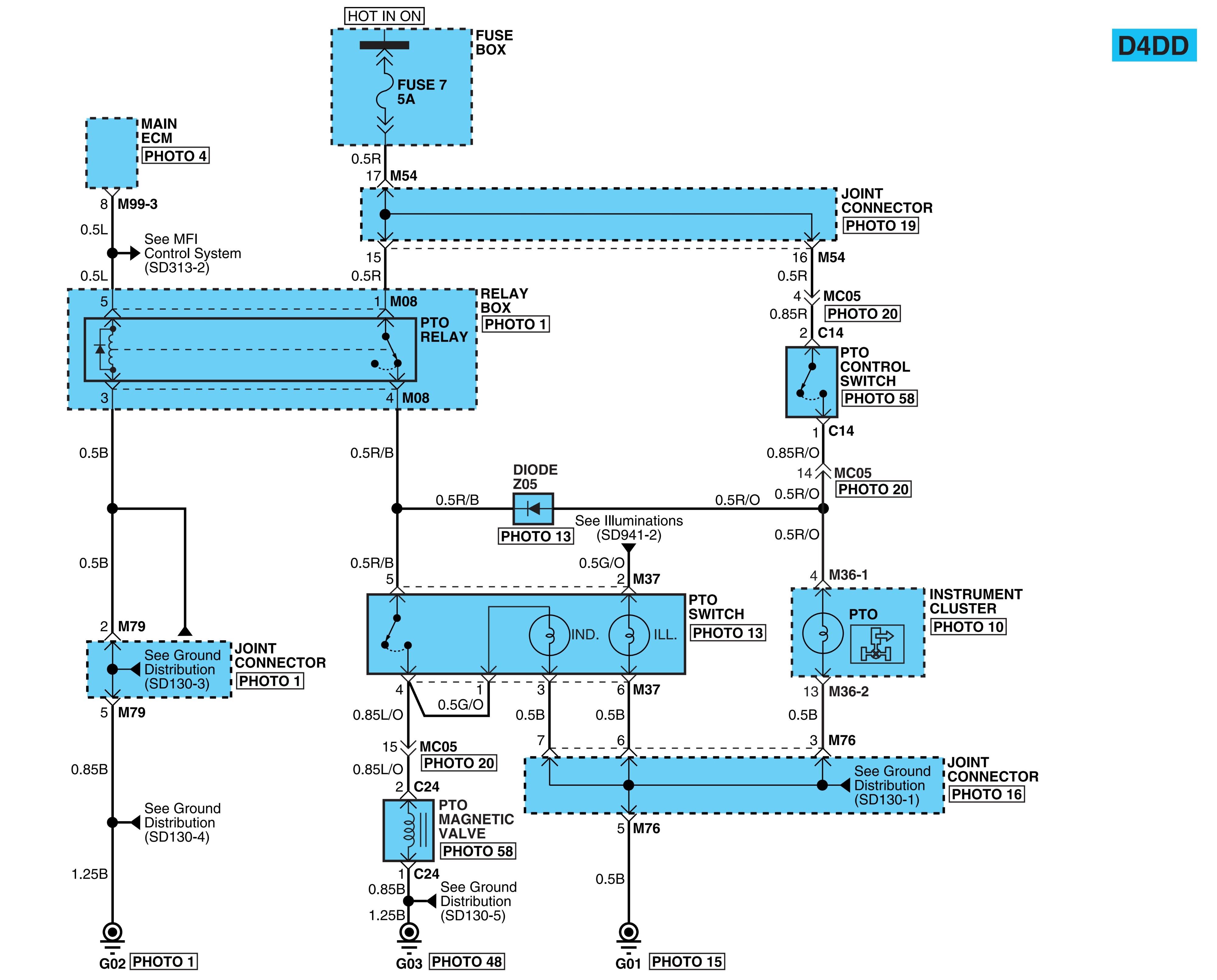
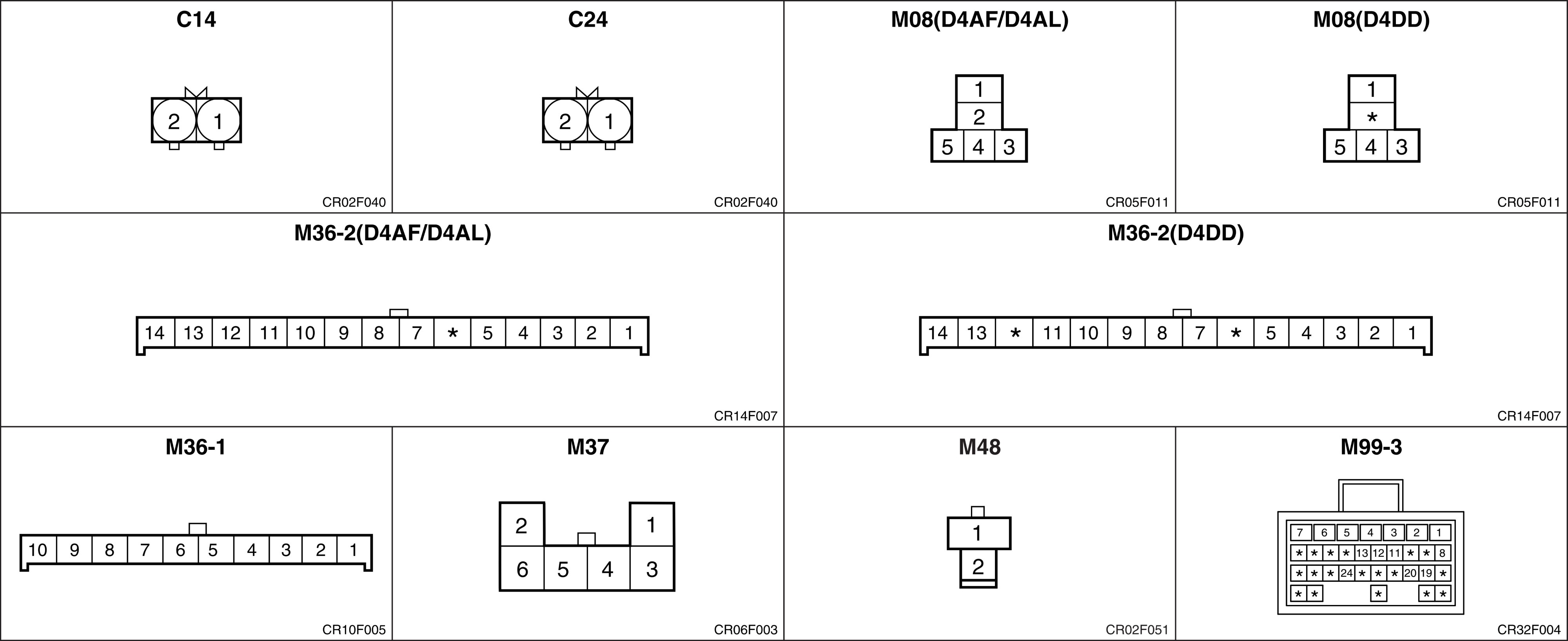
- P.T.O control system.
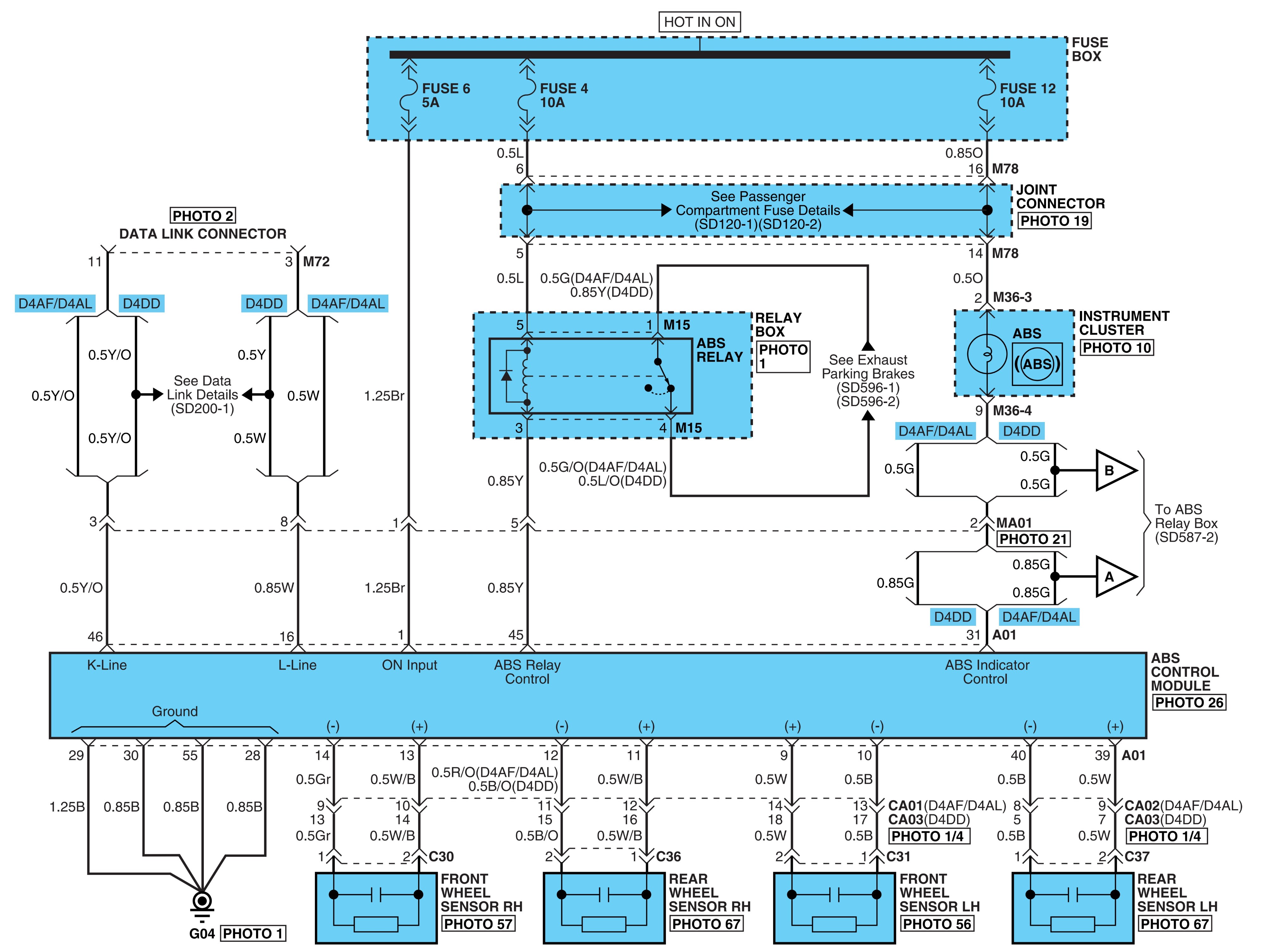
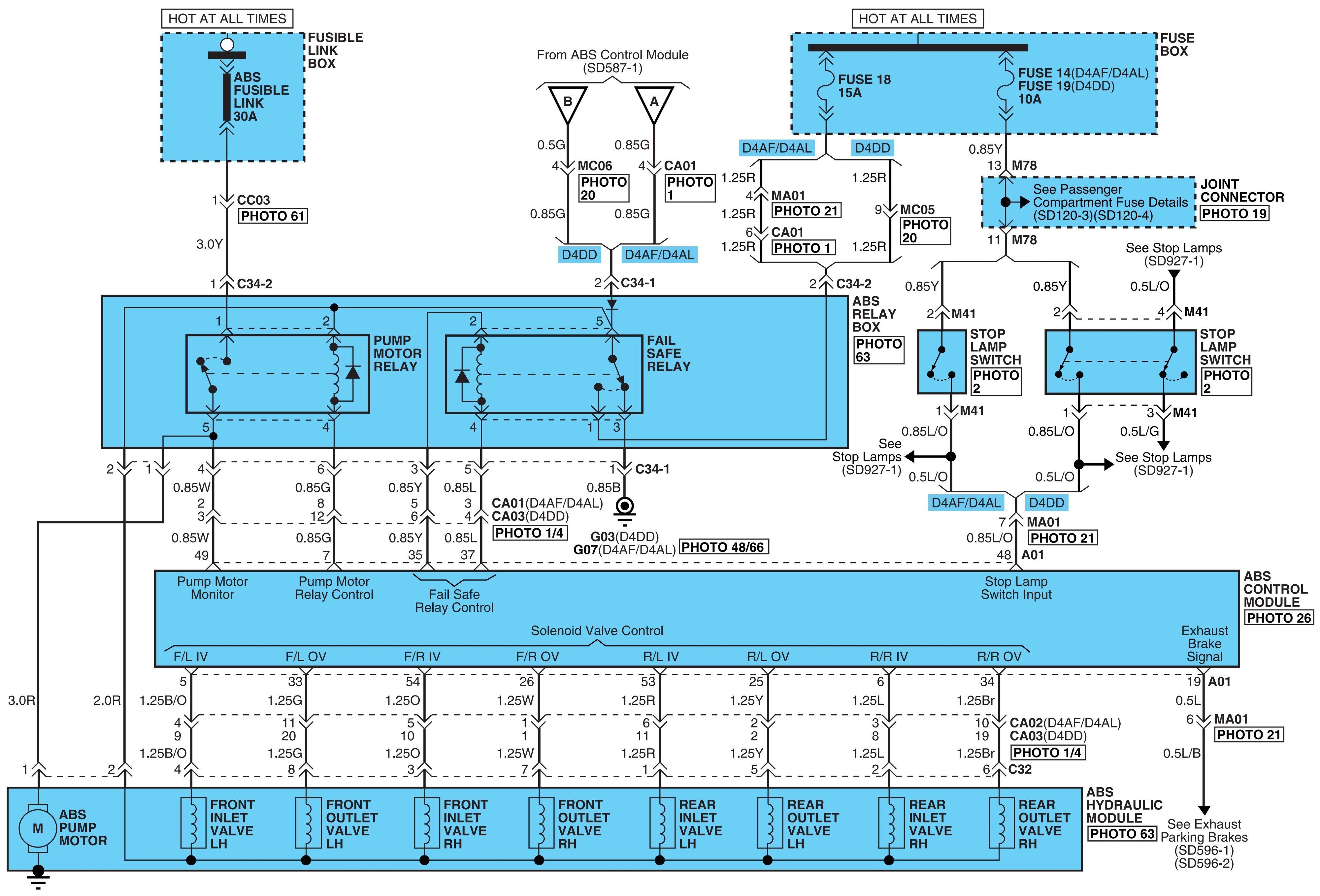
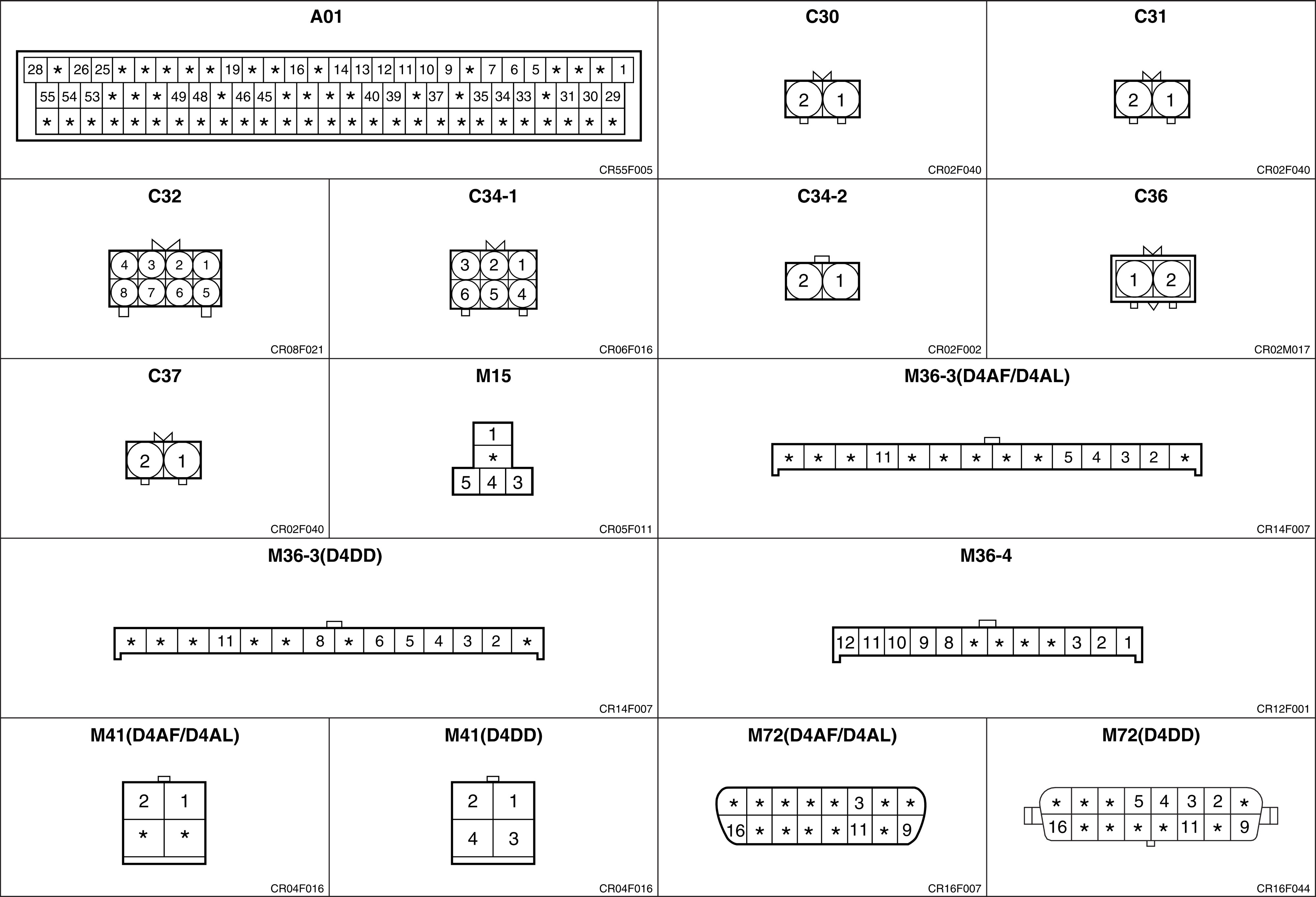
- ABS control system.
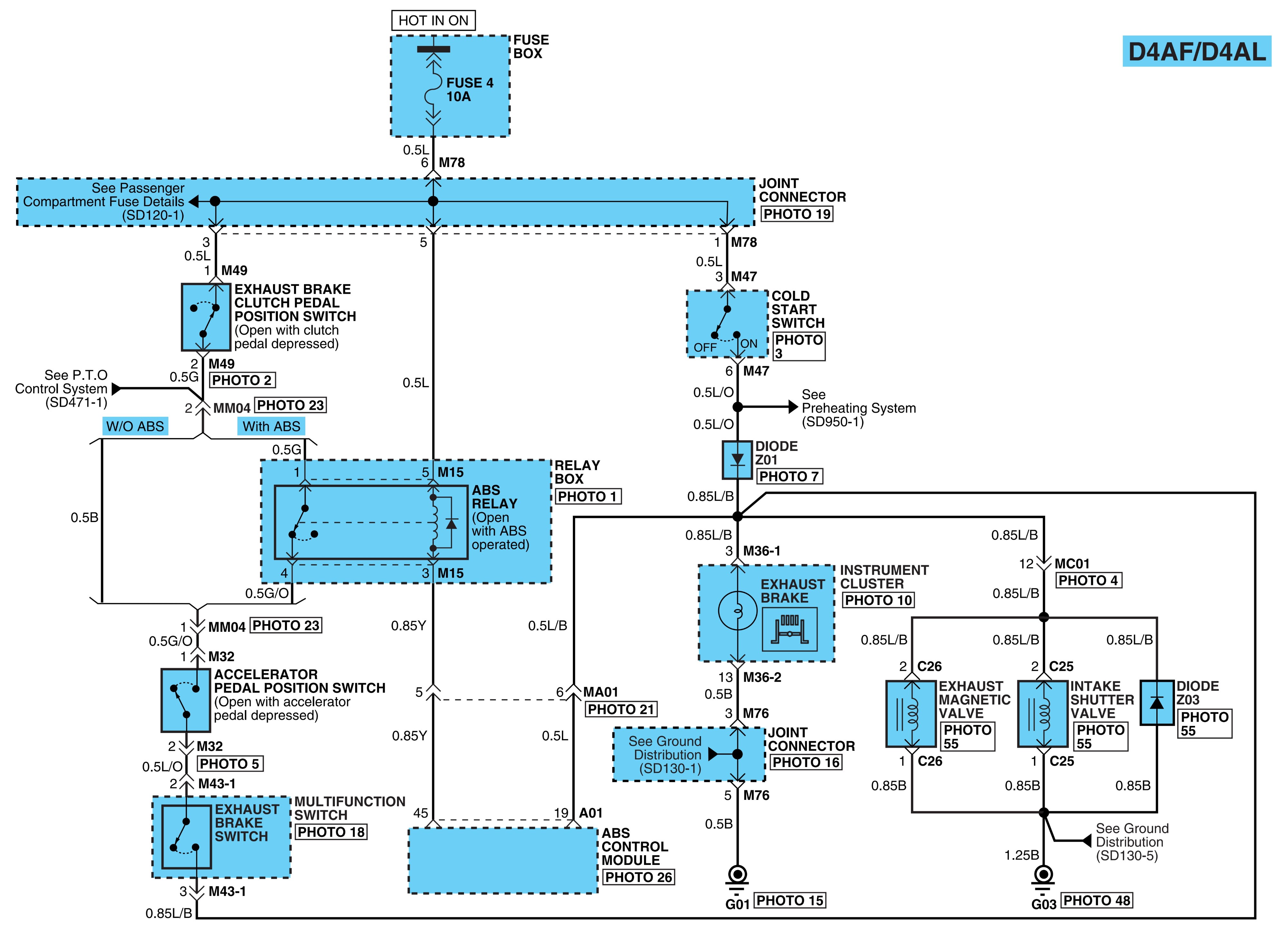
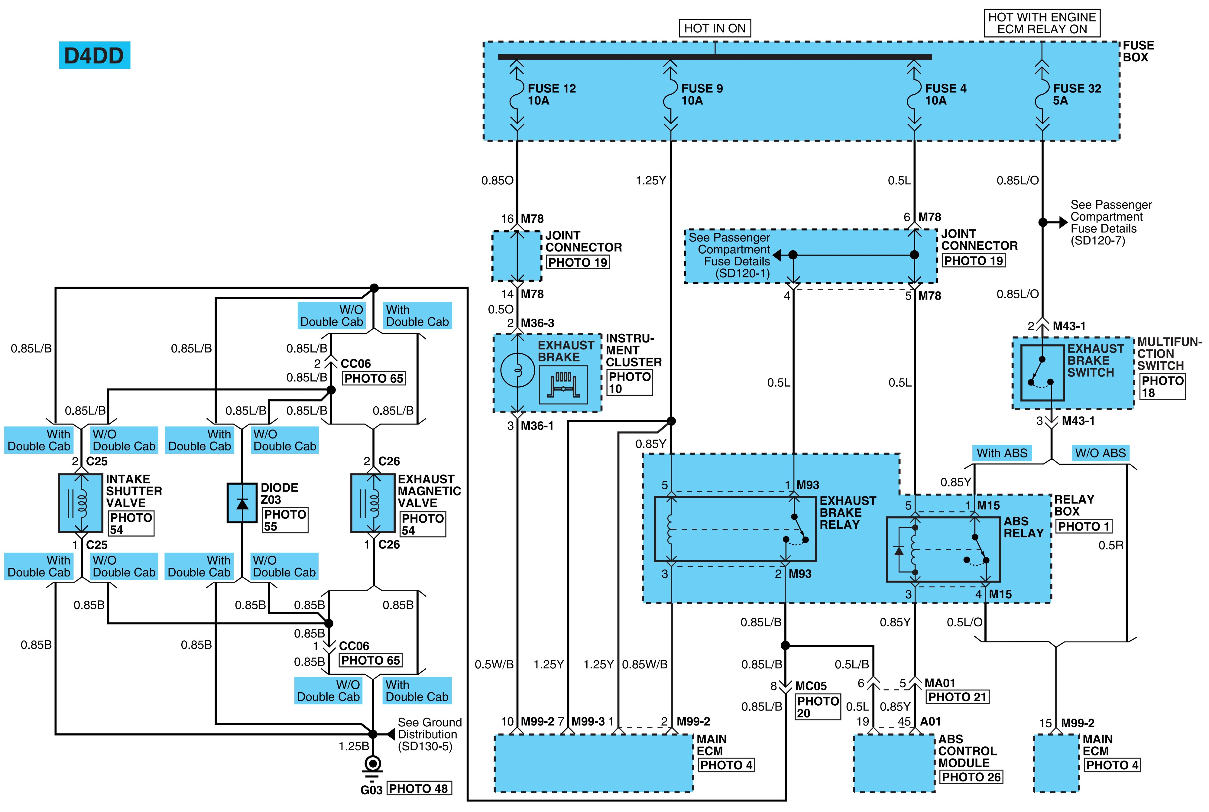
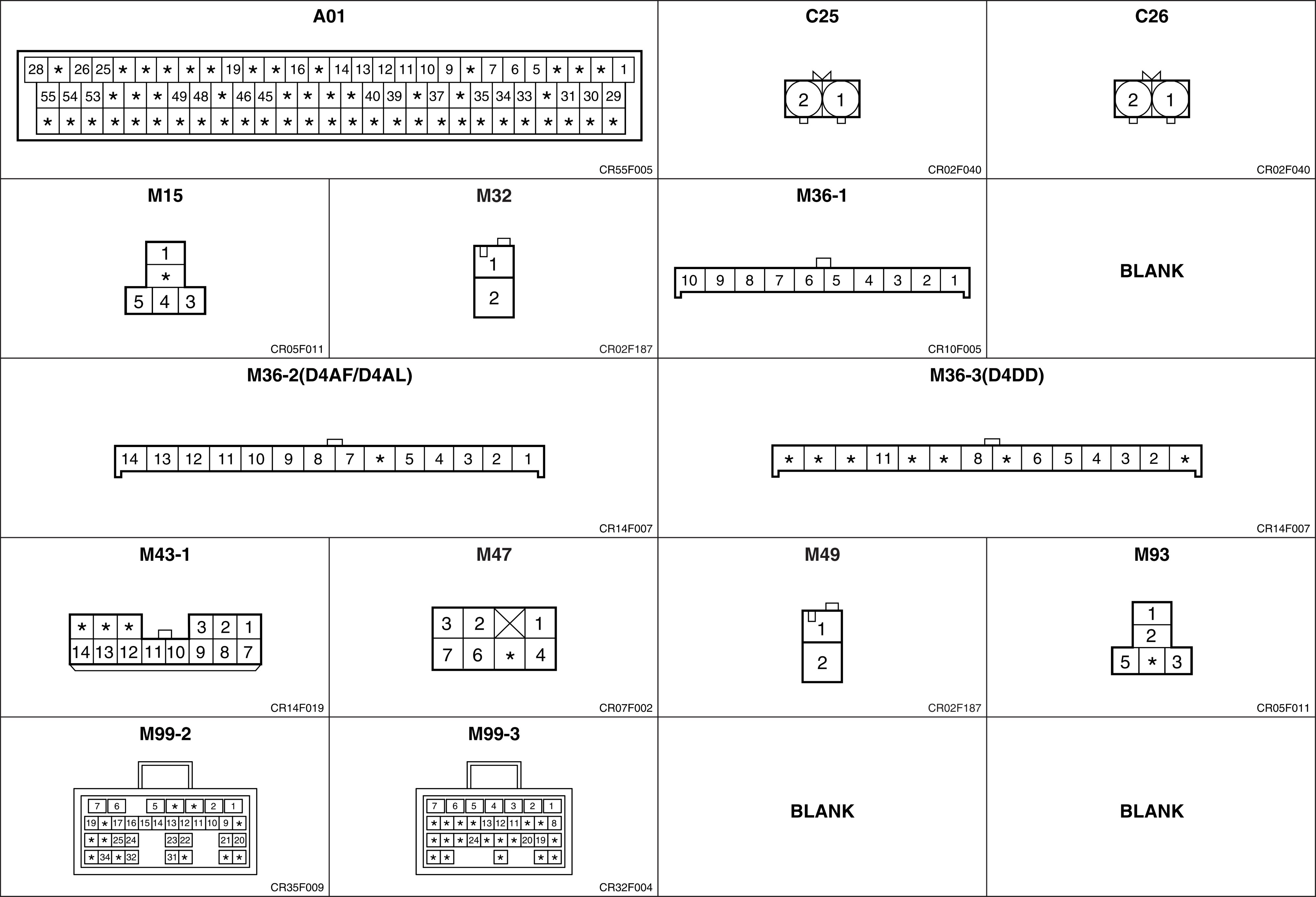
- Exhaust parking brakes.
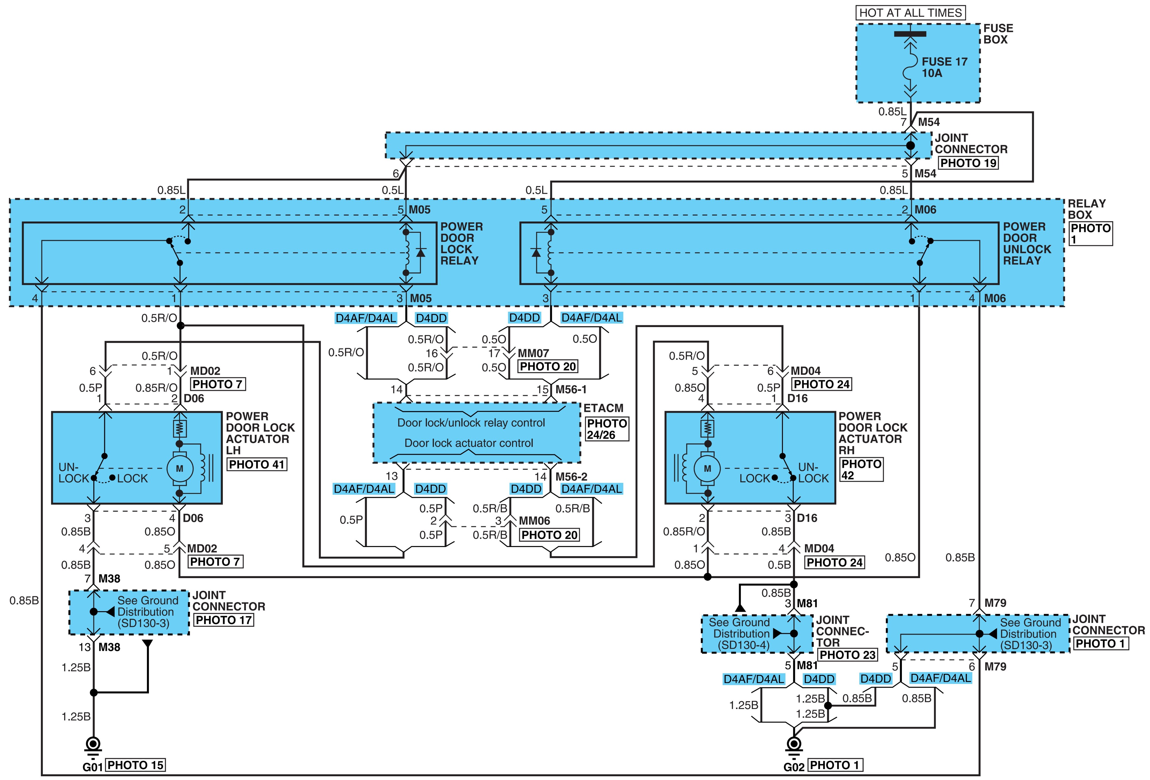
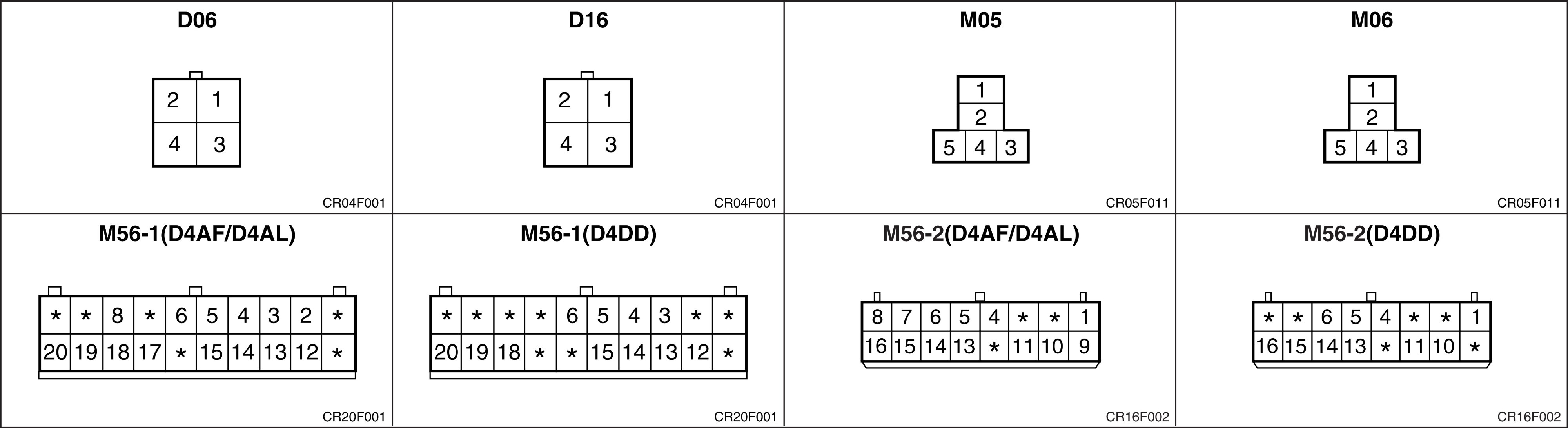
- Power door locks.
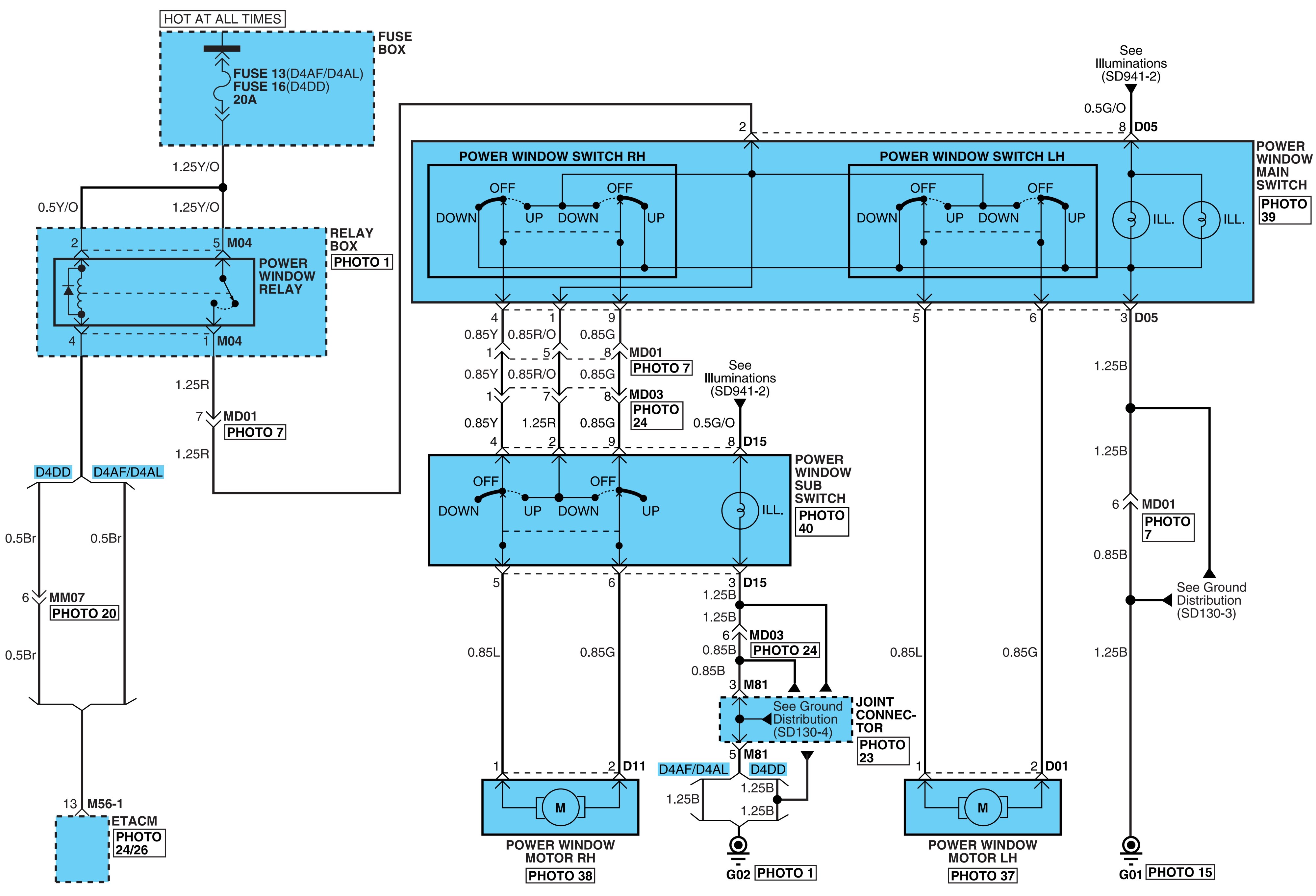
- Power windows.
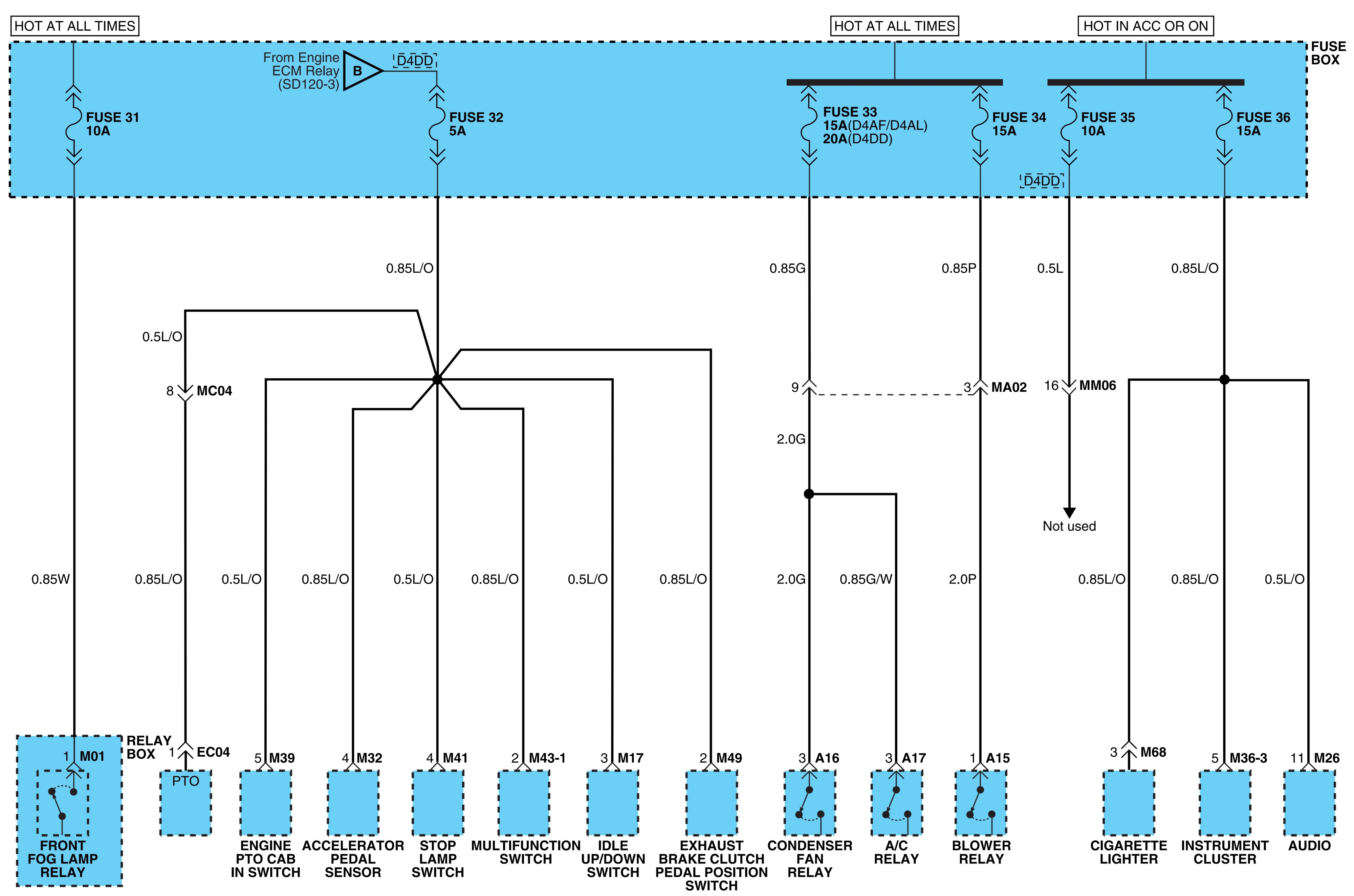
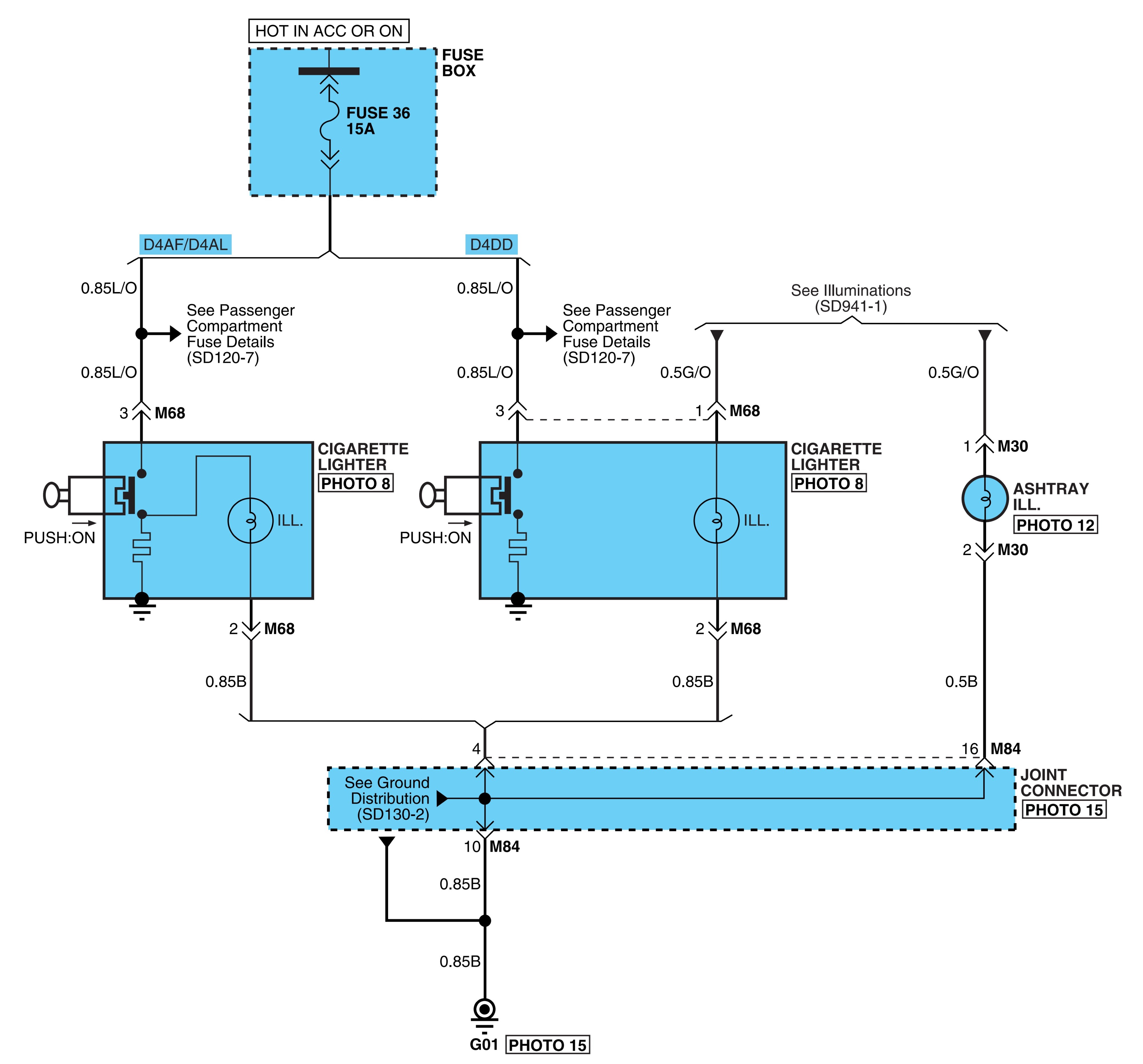
- Cigarette lighter.
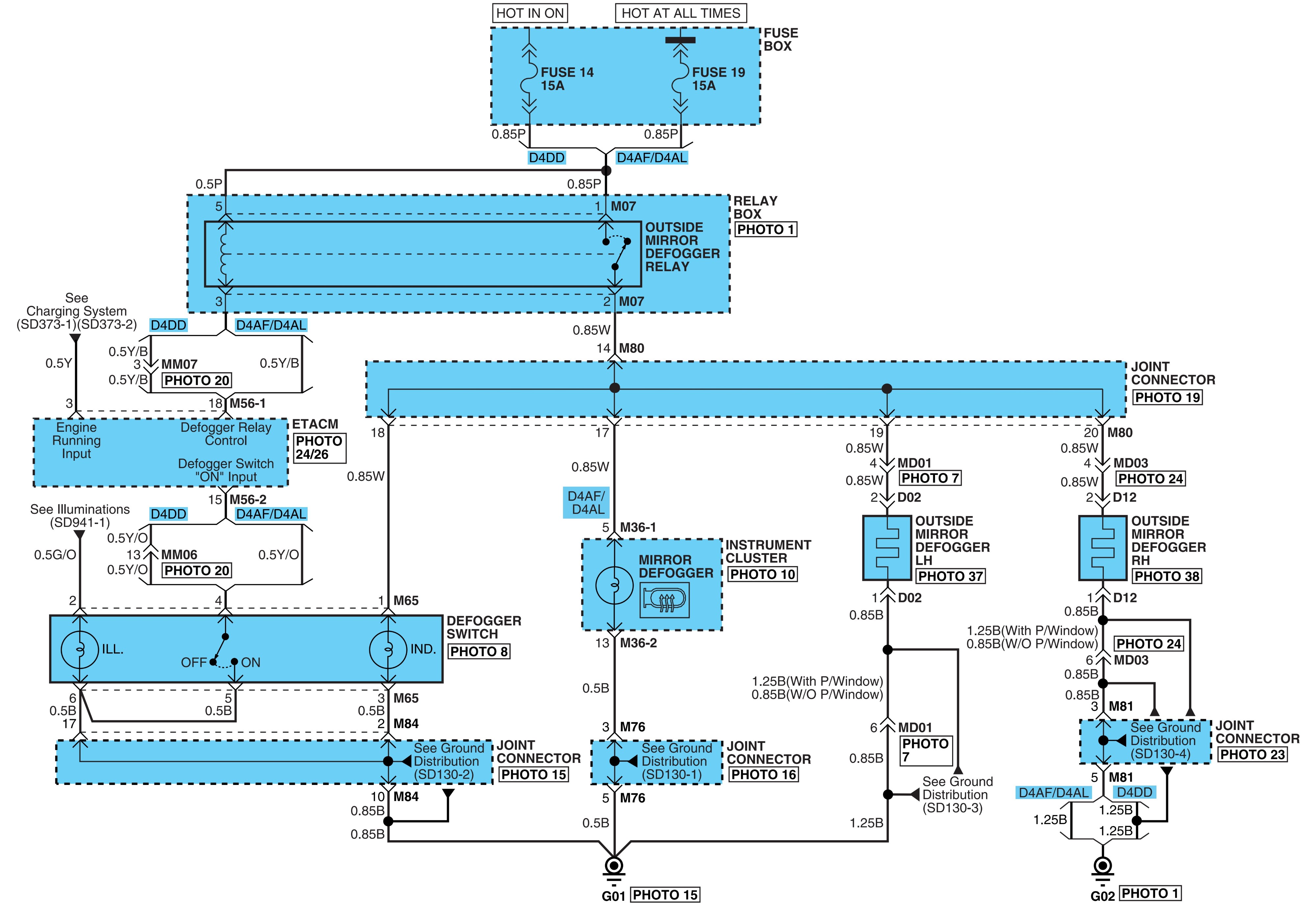
- Outside mirror defogger.
- Head lamps.
- Head lamp leveling device.
- Fog lamps.
- Turn & hazard lamps.
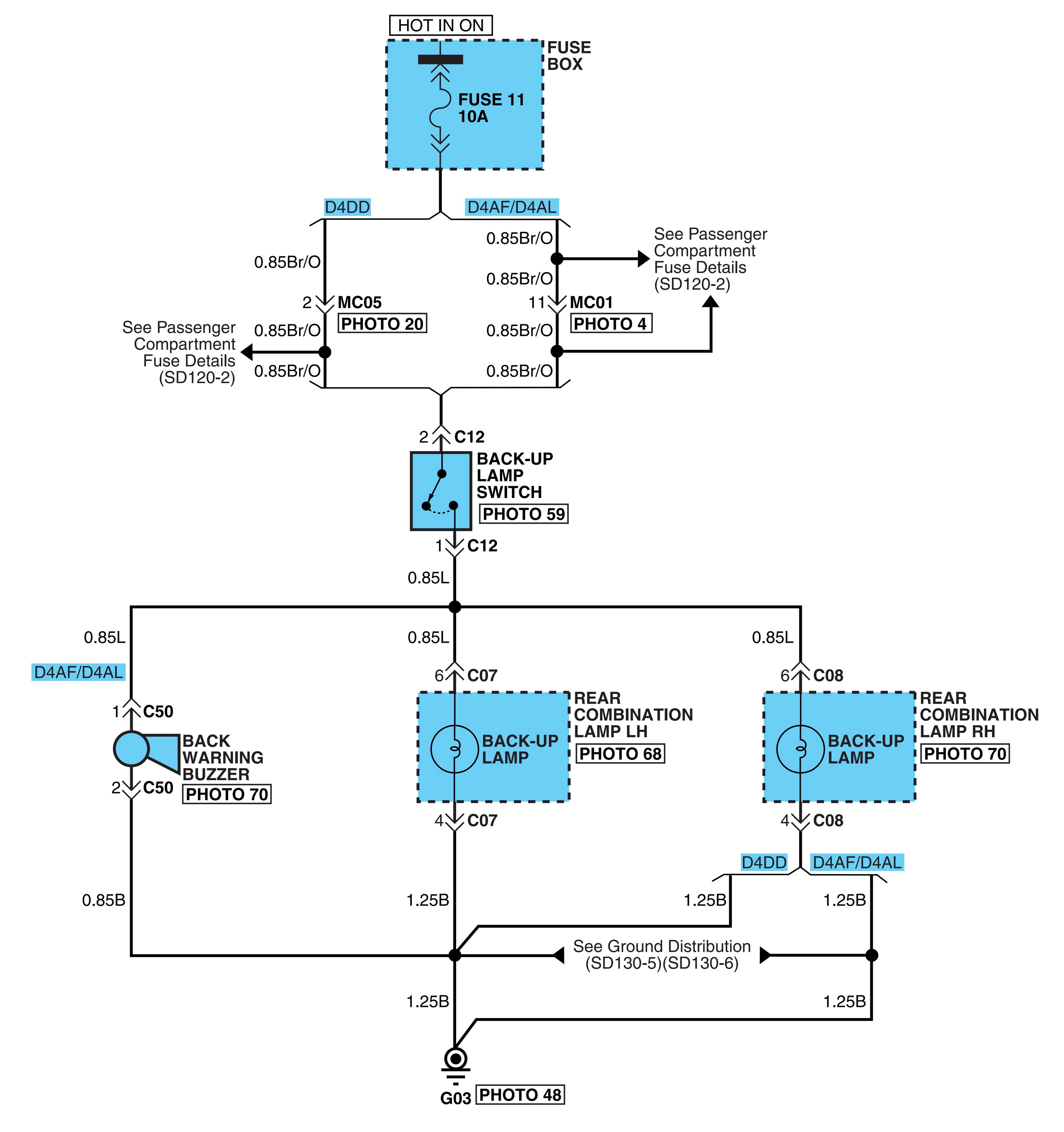
- Back-up lamps.
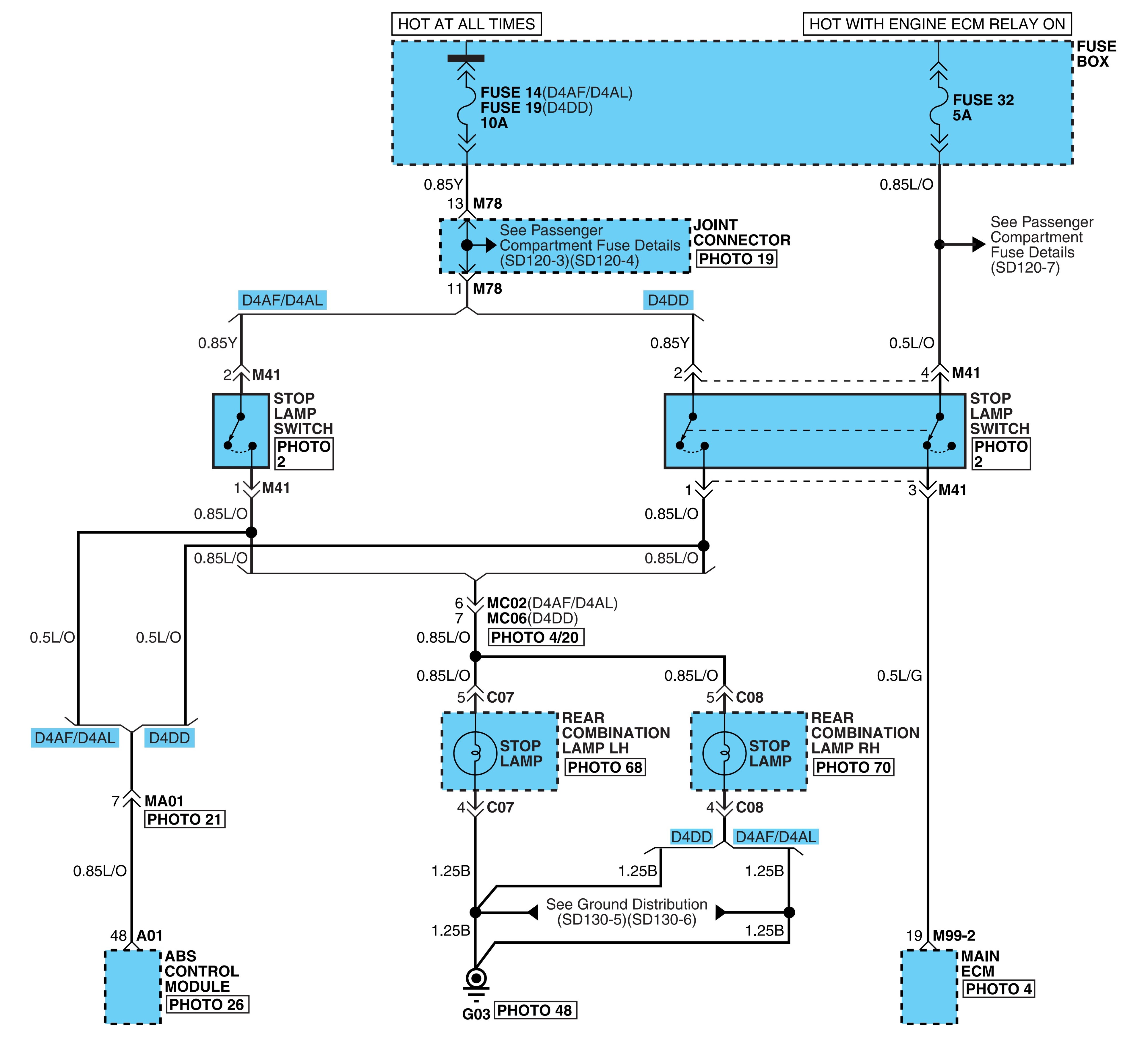
- Stop lamps.
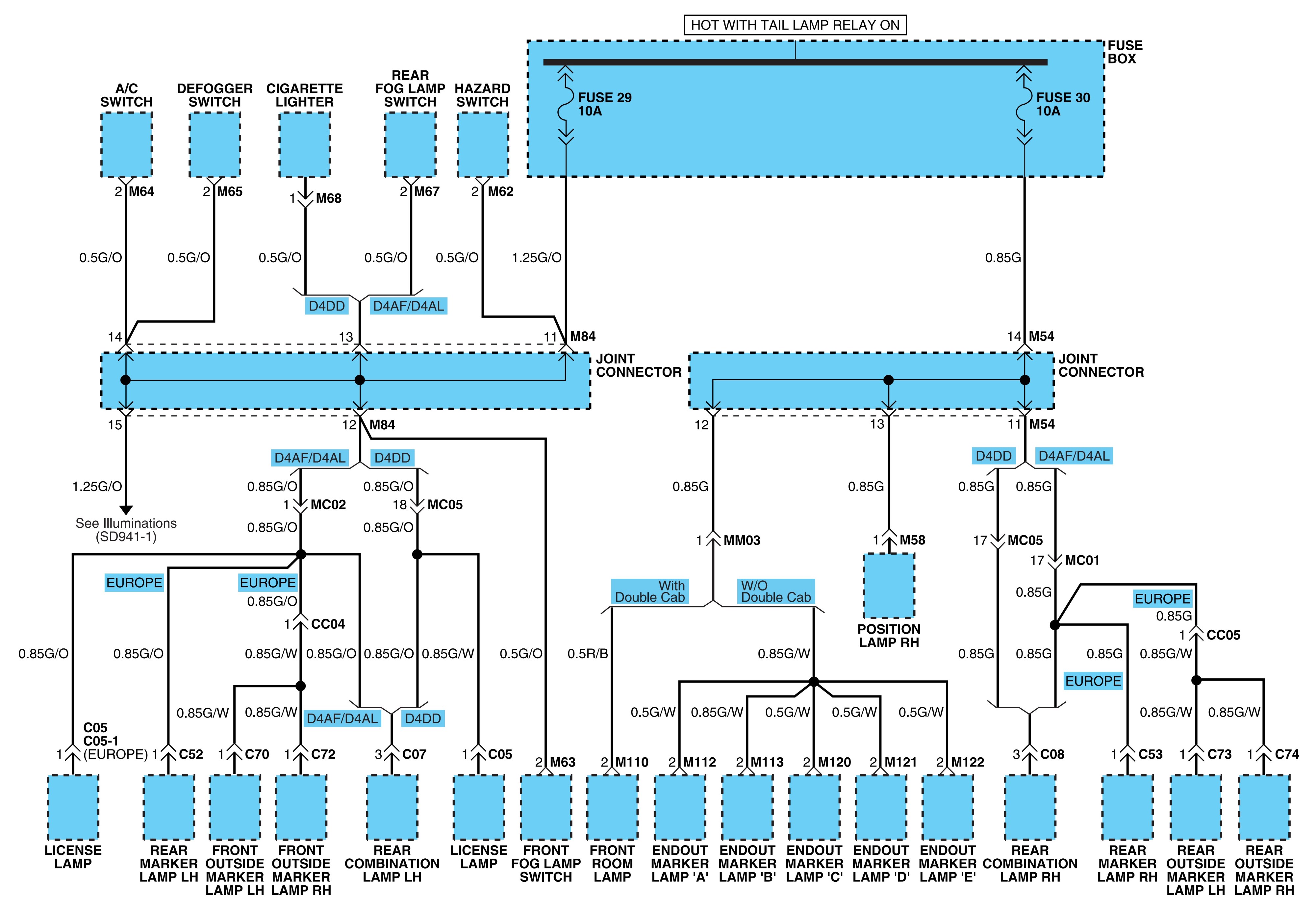
- Tail, parking & license lamps.
- Courtesy lamps.
- Working lamp & dump warning buzzer.
- Indicators & gauges.
- Illuminations.
- Tachograph.
- Preheating system.
- ETACS.
- Audio system.
- Horn.
- Blower & A/C controls.
- Wiper & washer.
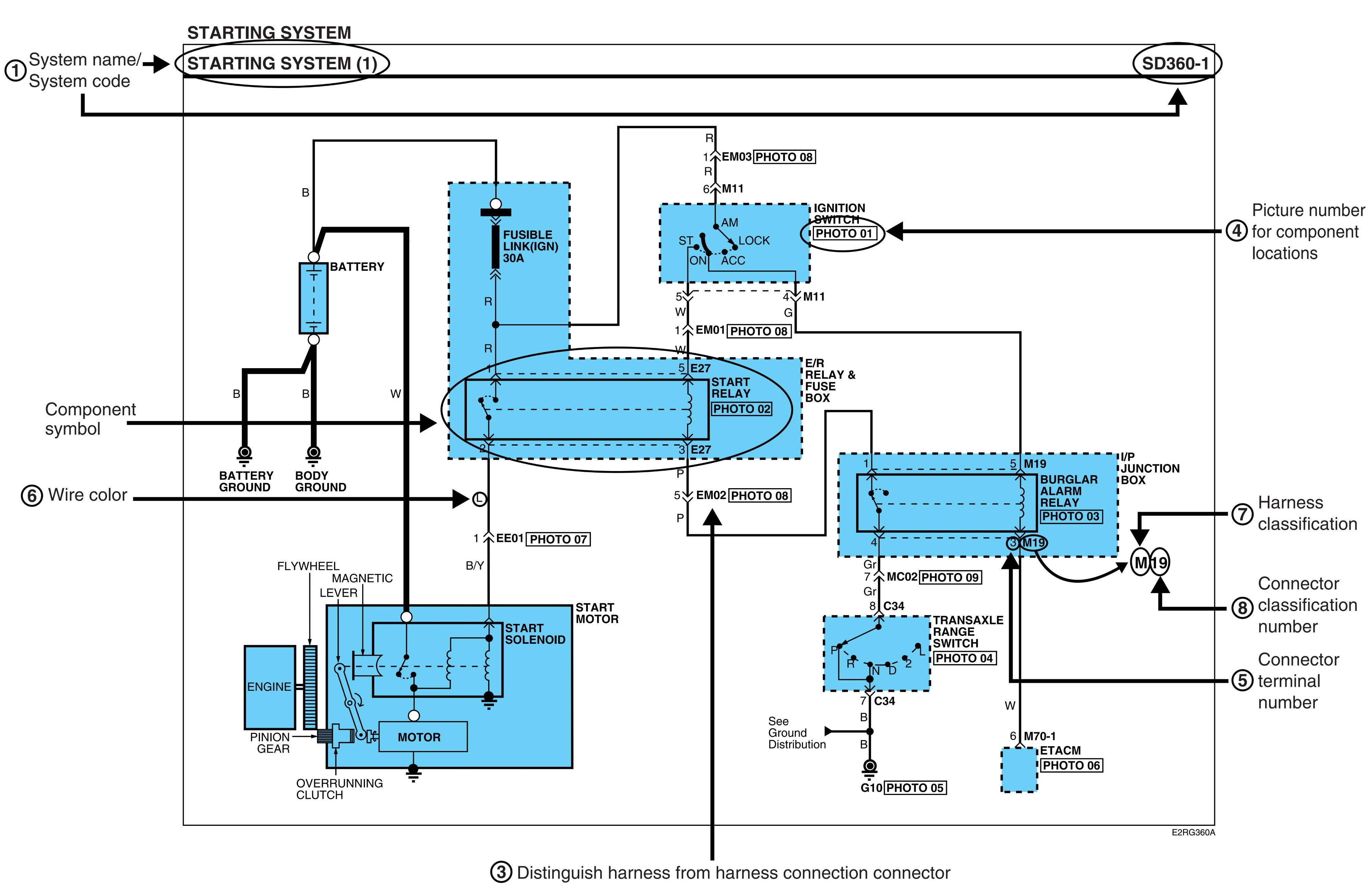
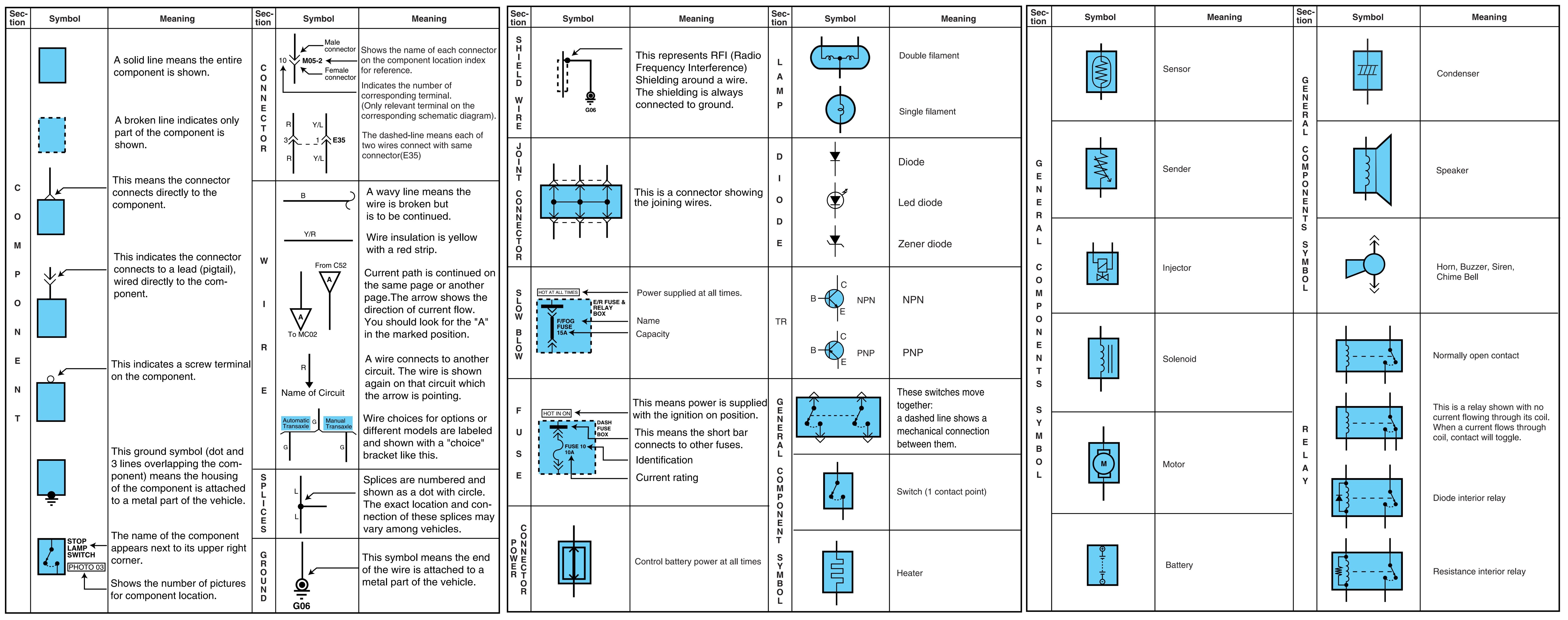
(1) Pages by system/ Name of Schematic diagram.
– Each page is consisted of circuits by system. This schematic diagram includes the path of electricity flow, connection condition for each switch, and the function of other relevant circuits at once. It is applicable to real service work.
– It is very important to understand relevant circuits exactly before troubleshooting diagnosis.
– Circuits by system depends upon part number and are indicated on schematic diagram index.
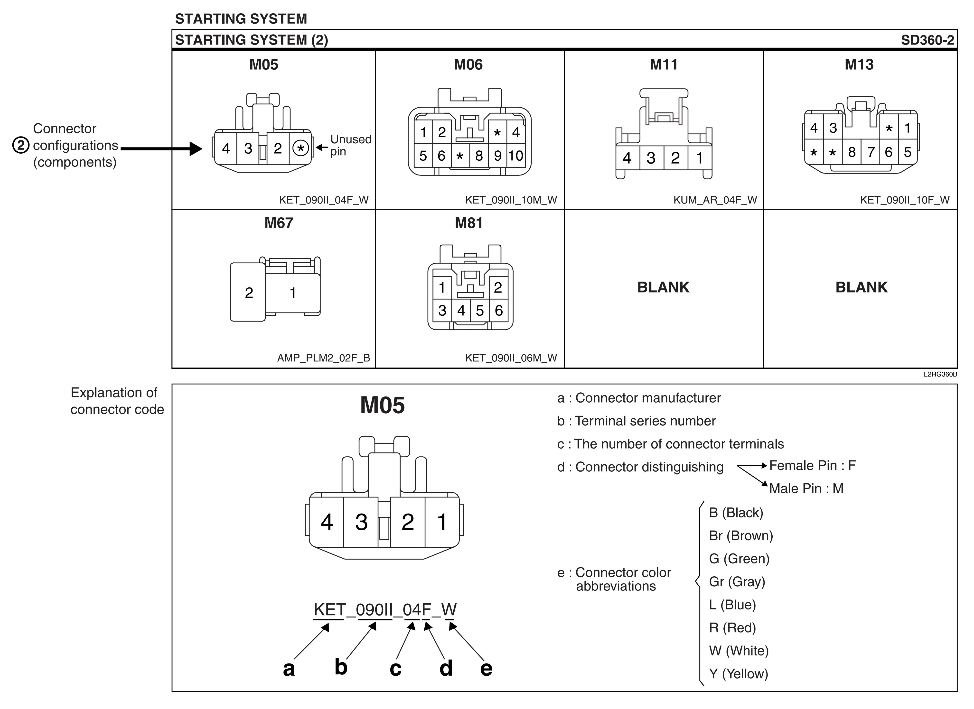
(2) Connector configuration (components).
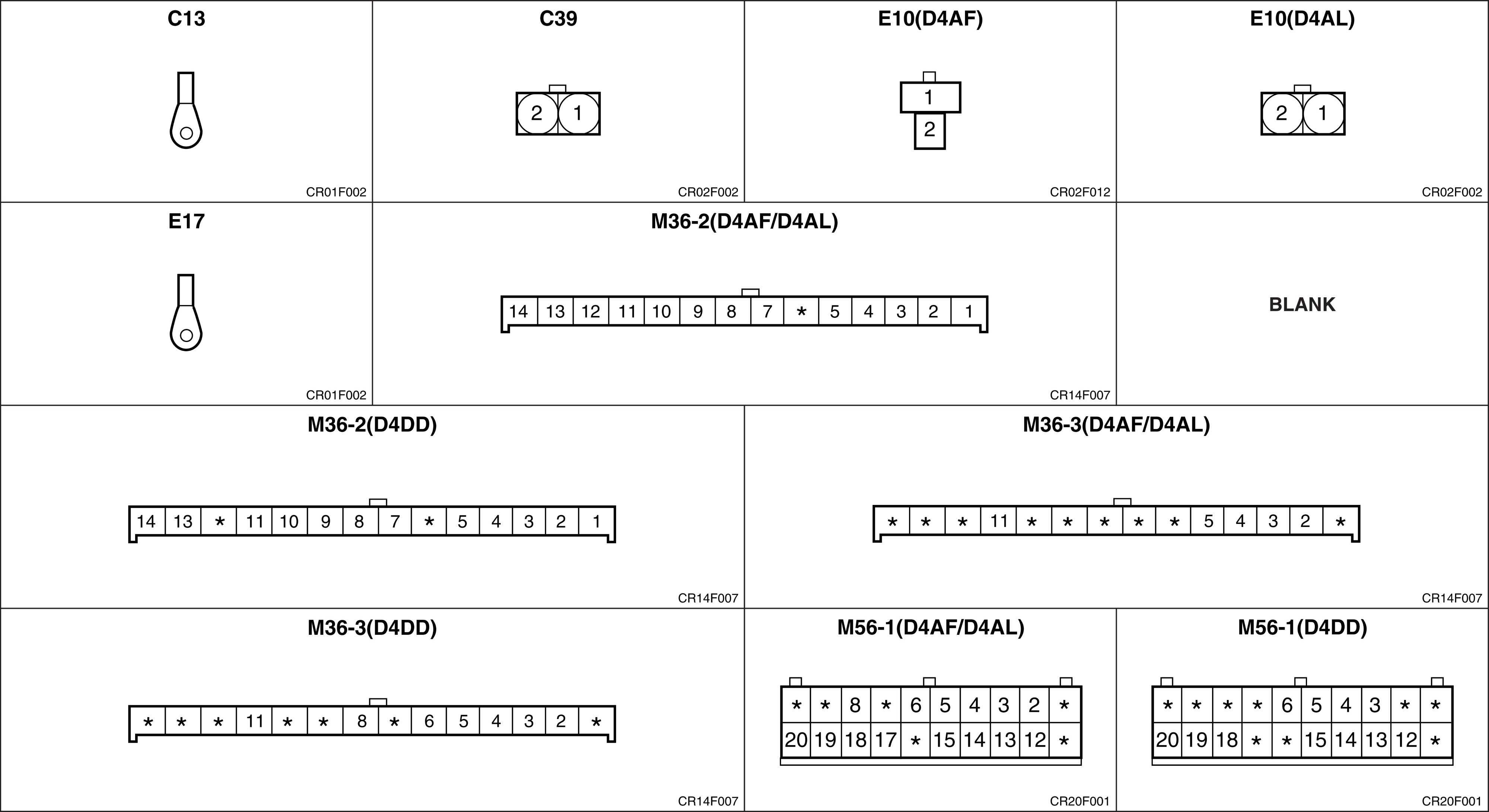
– The connector figure of components in the schematic diagram by system is indicated on the last page of schematic diagram.
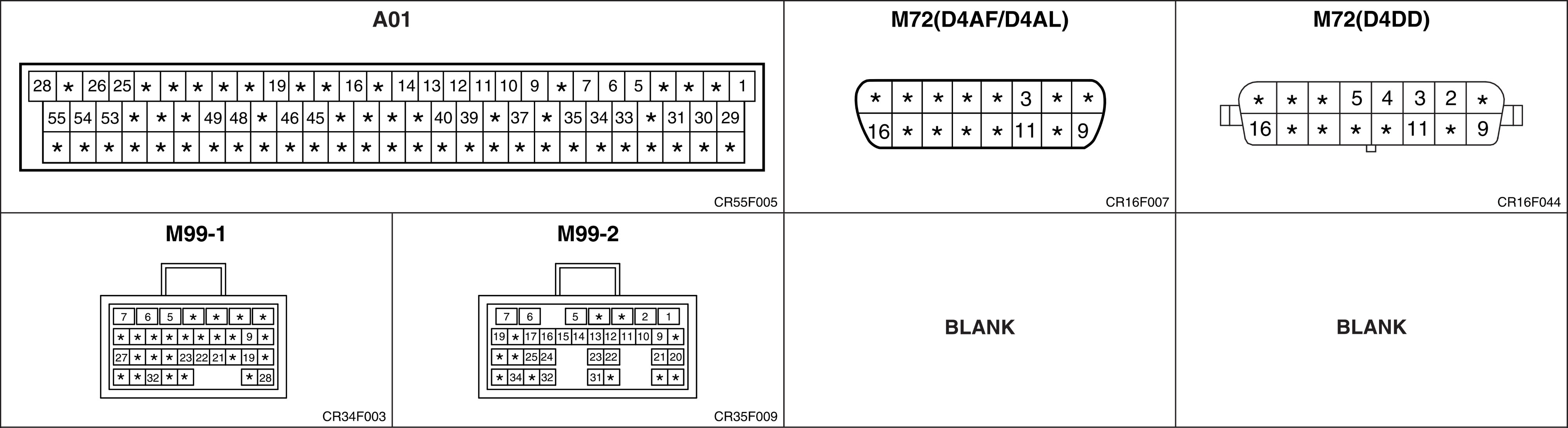
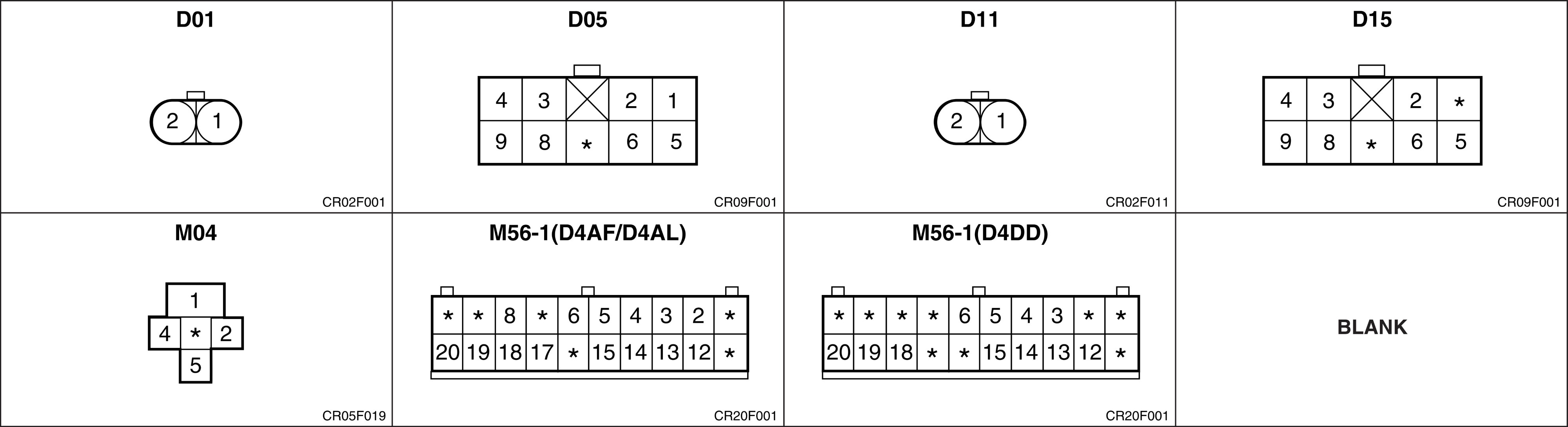
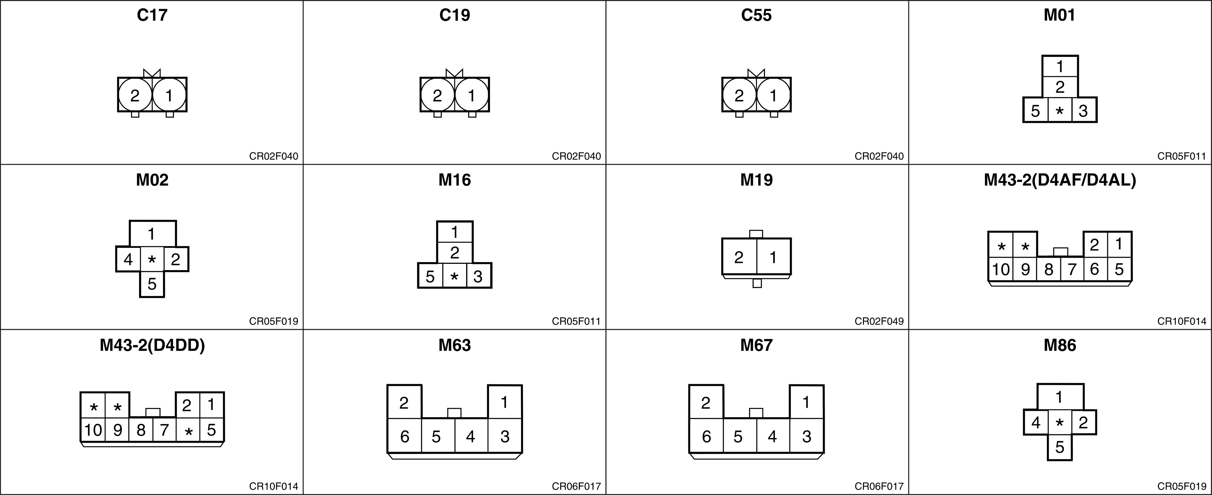
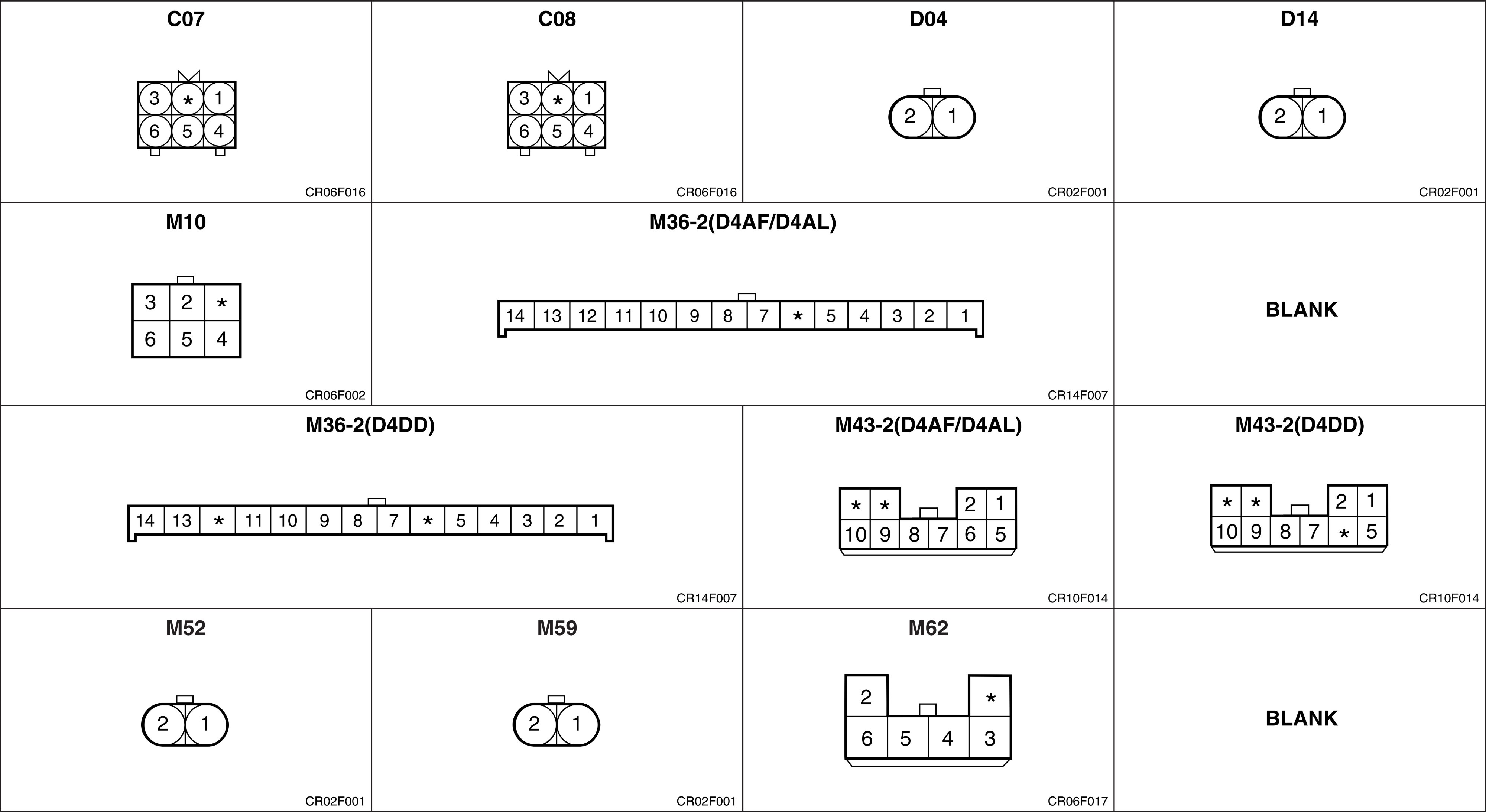
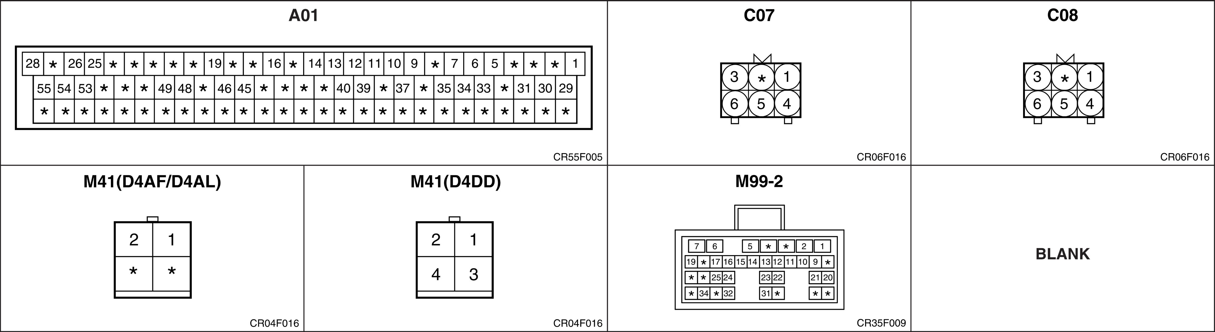
– It shows the front of the connector on the harness side when not to the harness connector. The terminal number on each connector can be obtained by following the pattern used in (5) connector view and numbering order. Unused terminals are marked with an asterisk (*).
(3) Connector configurations (connection between harnesses).
– When connecting the harness with connector between harnesses, it shows female and male connectors and indicates them on the connector configurations group.

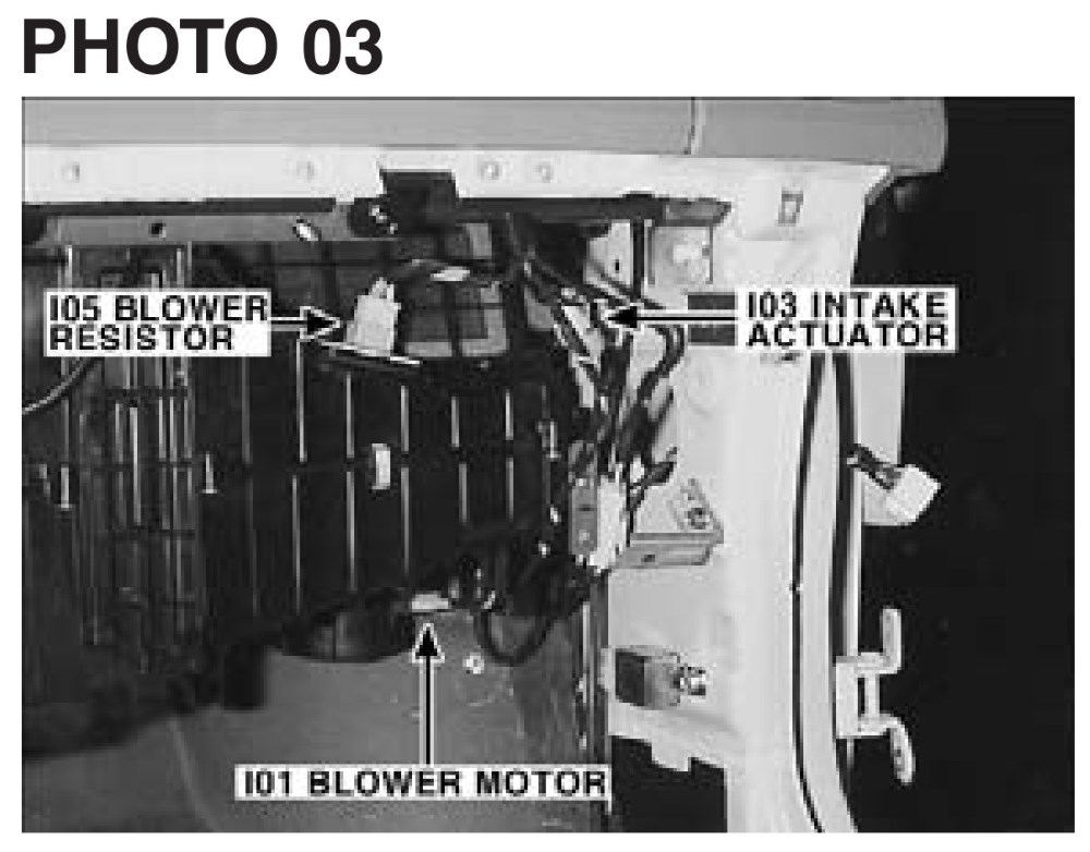
(4) Component locations.
– To find the components easily, a component locations diagram is indicated with “PHOTO NO” on the lower portion of the component name.
– To make it easy to distinguish connectors, the connector in the picture is indicated being installed in the vehicle.
(5) Connector view and numbering order.
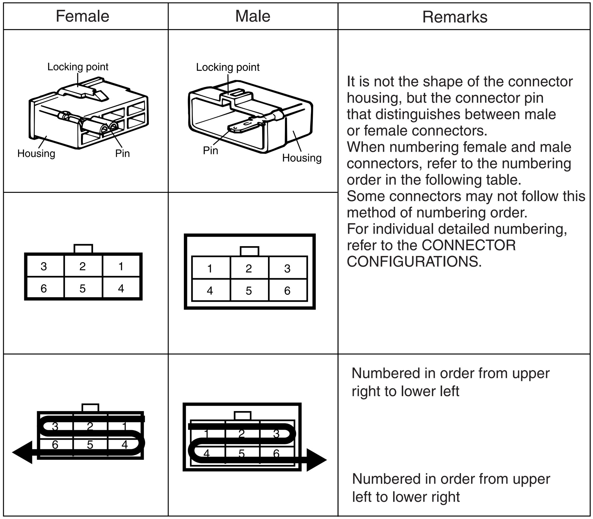
Note:
- Unless otherwise stated, all connector views are from the terminal side of the connector.
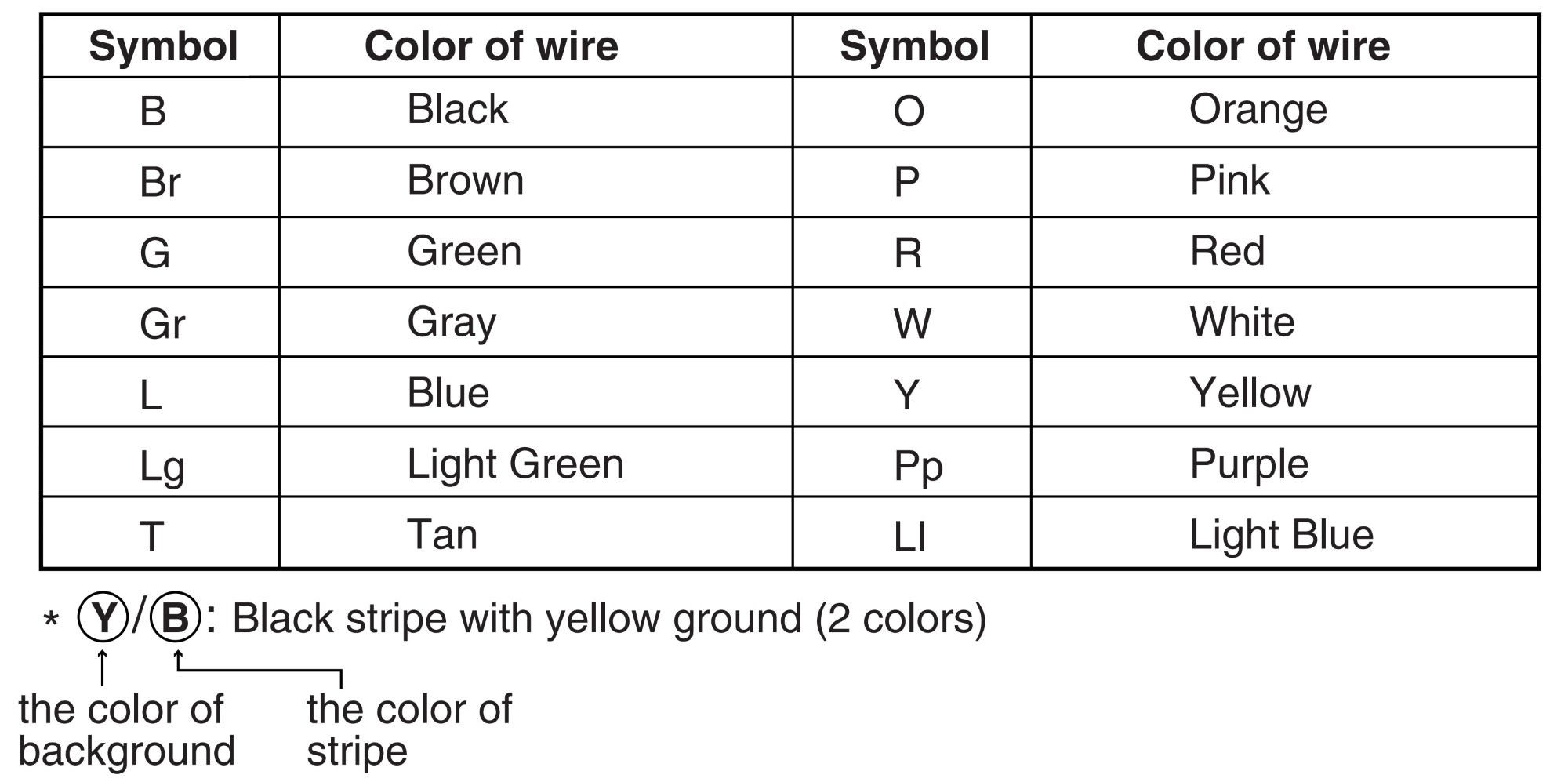
(6) Wire color abbreviations.
The following abbreviations are used to identify wire colors in the circuit schematics.
(7) Harness classification.
Electrical wiring connectors are classified according to the wiring parts in the Harness Layouts.
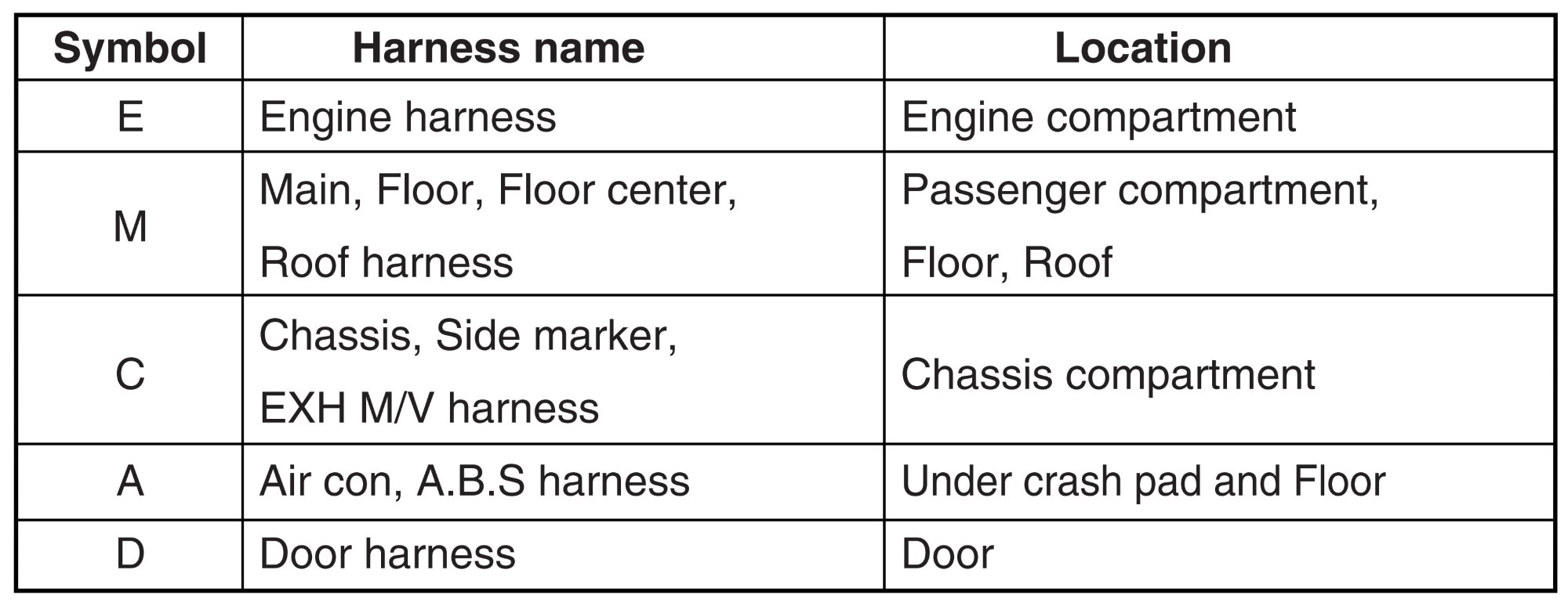
* It depends on vehicles, it is necessary to check the harness name symbol on the harness layouts for detailed symbol.
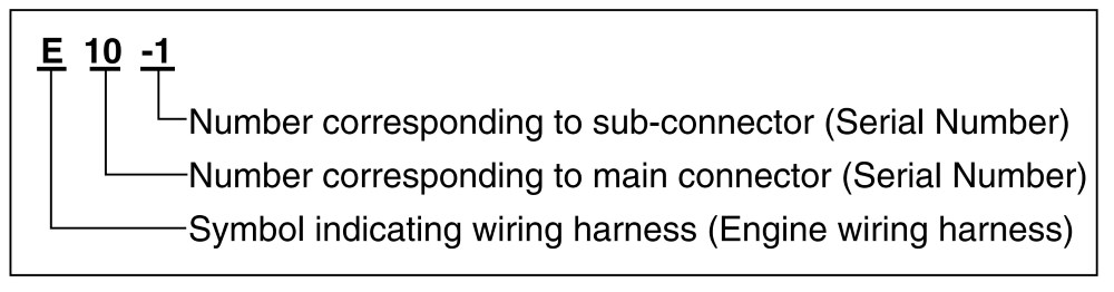
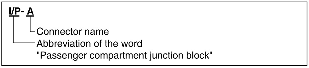
(8) Connector identification.
A connector identification symbol consists of a wiring harness location classification symbol corresponding to a wiring harness location and number corresponding to the connector.
These connector locations can be found in the HARNESS LAYOUTS.
For example:
Note:
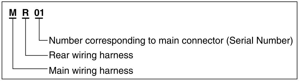
- Connectors which connect each wiring harness are represented by the following symbols.
For example:
Junction block identification.
A junction block identification symbol consists of a wiring harness location classification symbol corresponding to a wiring harness location and number corresponding to the connector in the junction block.
For example:
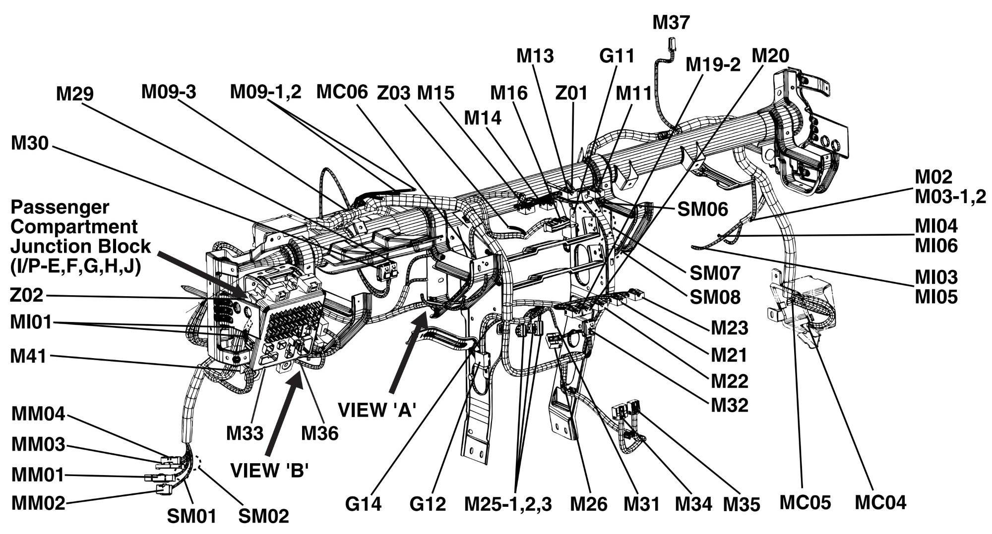
Harness layouts.
Harness layouts show the routing of the major wiring harnesses, the in-line connectors and the splices between the major harnesses.
These layouts will make electrical troubleshooting easier.
Troubleshooting procedures.
The following five-step troubleshooting procedure is recommended.
1. Verify the customer’s complaints.
Turn on all the components in the problem circuit to check the accuracy of the customer’s complaints. Note the symptoms.
Do not begin disassembly or testing until you have narrowed down the probable causes.
2. Read and analyze the schematic diagram.
Locate the schematic for the problem circuit. Determine how the circuit is supposed to work by tracing the current paths from the power source through the system components to ground. If you do not understand how the circuit should work, read the circuit operation text. Also check other circuits that share with the problem circuit. The name of circuits that share the same fuse, ground, or switch, for example, are referred to on each diagram. Try to operate any shared circuits you did not check in step 1. If the shared circuit works, the shared wiring is okay, and the cause must be within the wiring used only by the problem circuit.
If several circuits fail at the same time, the fuse or ground is a likely cause.
3. Inspect the circuit/ component with the problem isolated.
Make a circuit test to check the diagnosis you made in step 2. Remember that a logical, simple procedure is the key to efficient troubleshooting. Narrow down the probable causes using the troubleshooting hints and system diagnosis charts.
Test for the most likely cause of failure first.
Try to make tests at points that are easily accessible.
4. Repair the problem.
Once the problem is found, make the necessary repairs.
5. Make sure the circuit works.
Repeat the system check to be sure you have repaired the problem. If the problem was a blown fuse, be sure to test all of the circuits on that fuse.
Troubleshooting equipment.
Voltmeter and test lamp.
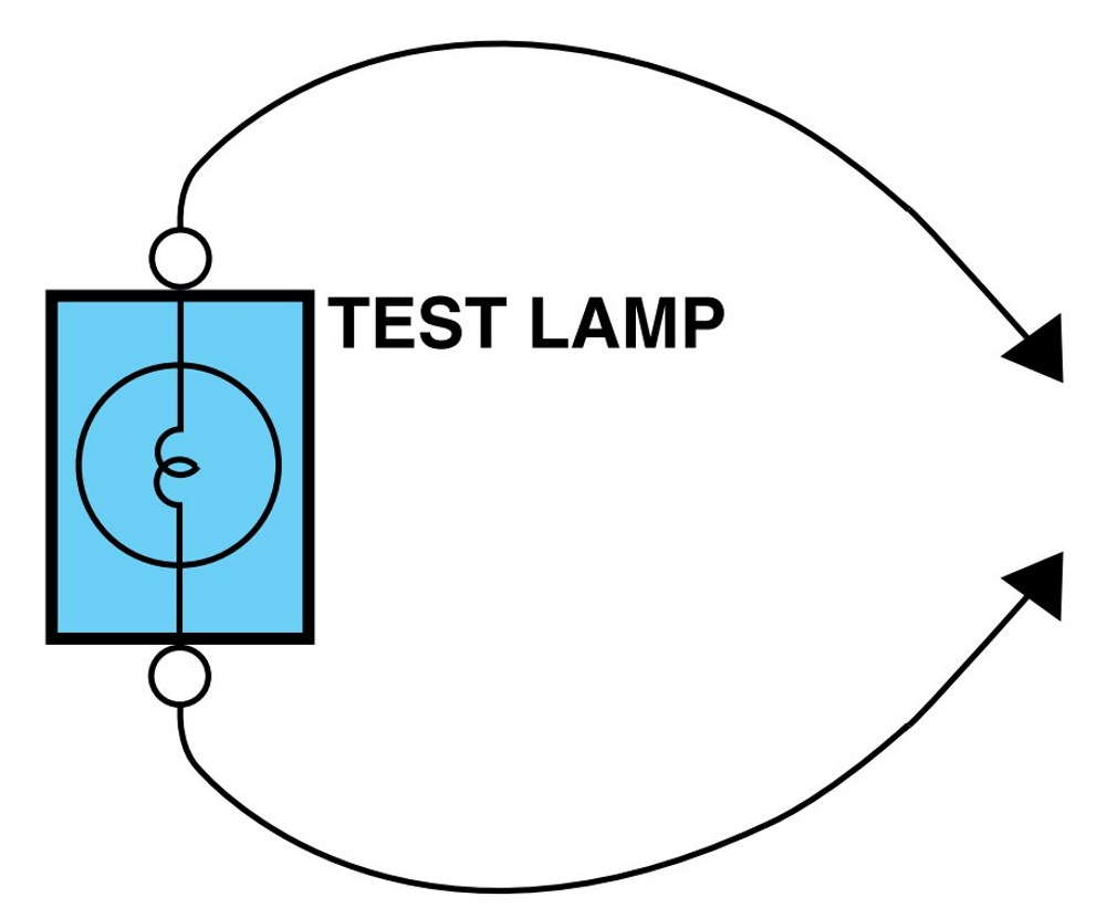
Use a test lamp or a voltmeter on circuits without solidstate units and use a test lamp to check for voltage. A test lamp is made up of a 12-volt light bulb with a pair of leads attached. After grounding one lead, touch the other lead to various points along the circuit where voltage should be present.
When the bulb goes on, there is voltage at the point being tested.
Caution.
- A number of circuits include solid-state modules, such as the Engine Control Module (ECM), used with computer command control injection. Voltage in these circuits should be tested only with a 10-megaohm or higher impedance digital multimeter. Never use a test lamp on circuits that contain solid state modules. Damage to the modules may result.
A voltmeter can be used in place of a test lamp. While a test lamp shows whether the voltage is present or not, a voltmeter indicates how much voltage is present.
Self-powered test lamp and ohmmeter.
Use a self-powered test lamp or an ohmmeter to check for continuity. The ohmmeter shows how much resistance there is between two points along a circuit. Low resistance means good continuity.
Caution.
- Never use a self-powered test lamp on circuits that contain solid state modules. Damage to these modules may result.
An ohmmeter can be used in place of a self-powered test lamp.
The ohmmeter shows how much resistance there is between two points along a circuit. Low resistance means good continuity.
Circuits which include any solid-state devices should be tested only with a 10-megaohm or higher impedance digital multimeter. When measuring resistance with a digital multimeter, the battery negative terminal should be disconnected. Otherwise, there may be incorrect readings. Diodes and solid-state devices in a circuit can make an ohmmeter give a false reading.
To find out if a component is affecting a measurement, take one reading, reverse the leads and take a second reading.
If different the solid-state device is affecting the measurement.
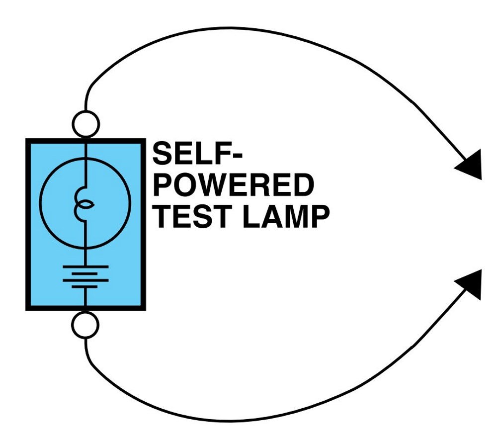
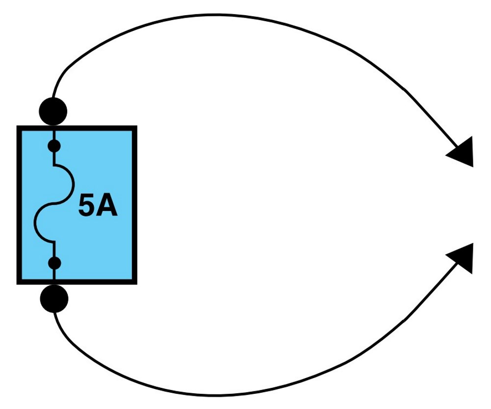
Jumper wire with fuse.
Use a jumper wire with a fuse to by-pass an open circuit.
A jumper wire is made up of an in-line fuse holder connected to a set of test leads. This tool is available with small clamp connectors providing adaption to most connectors without damage.
Caution.
- Do not use a fuse with a higher rating than the specified fuse that protects the circuit being tested. Do not use this tool in any situation to substitute an input or output at the solid-state control module, such as ECM, TCM, etc.
Short finder.
A short finder is available to locate a short to ground. The short finder creates a pulsing magnetic field in the shorted circuit and shows you the location of the short through body trim or sheet metal.
Troubleshooting test.
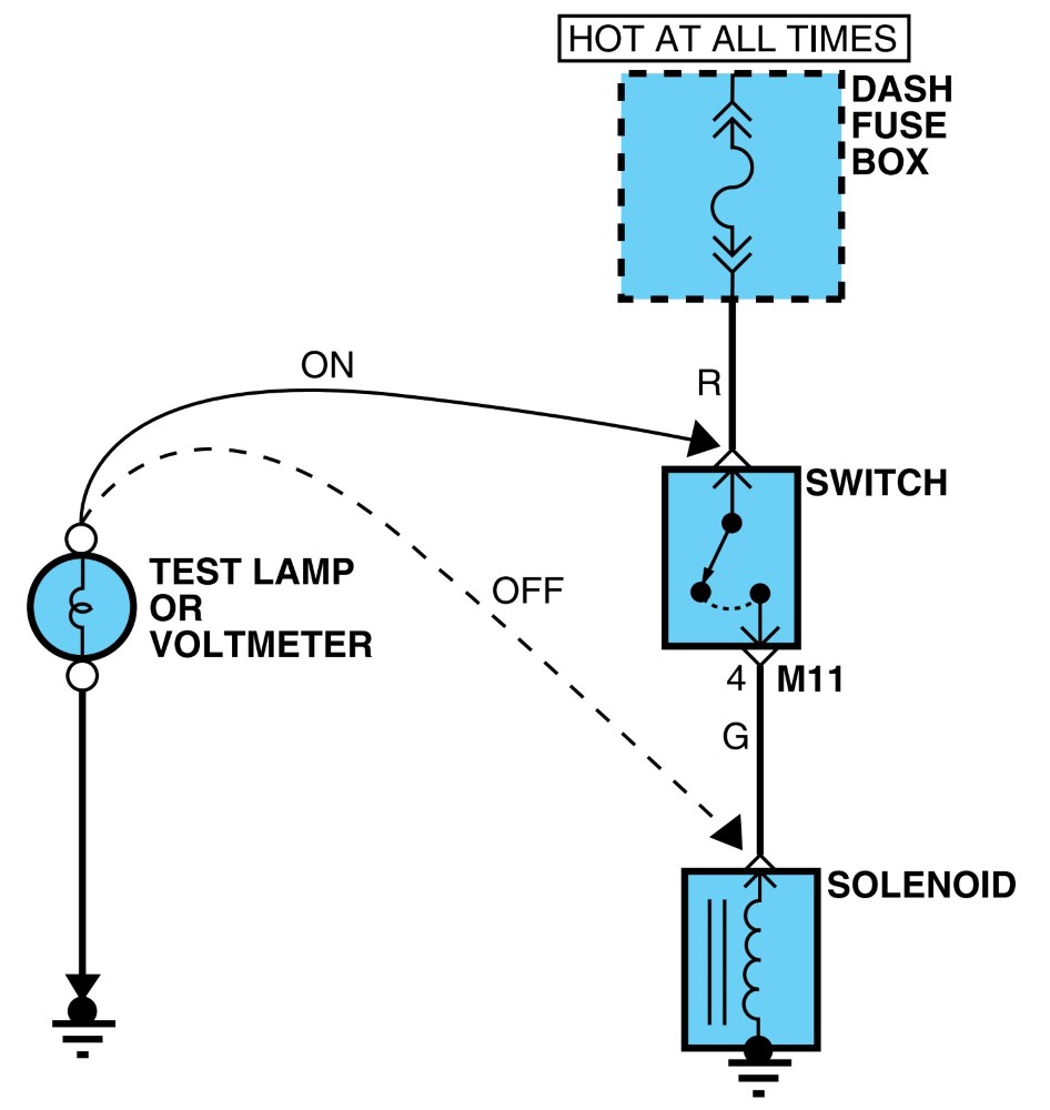
1. Testing for voltage.
This test measures voltage in a circuit. When testing for voltage at a connector, you do not have to separate the two halves of the connector. lnstead, probe the connector from the back (backprobe). Always check both sides of the connector because dirt and corrosion between its contact surfaces can cause electrical problems.
A. Connect one lead of a test lamp or voltmeter to a ground. If you are using a voltmeter, be sure it is the voltmeter’s negative test lead you have connected to ground.
B. Connect the other lead of the test lamp or voltmeter to a selected test point (connector or terminal).
C. If the test lamp glows, there is voltage present. If you are using a voltmeter, note the voltage reading. A loss of more than 1 volt from specification indicates a problem.
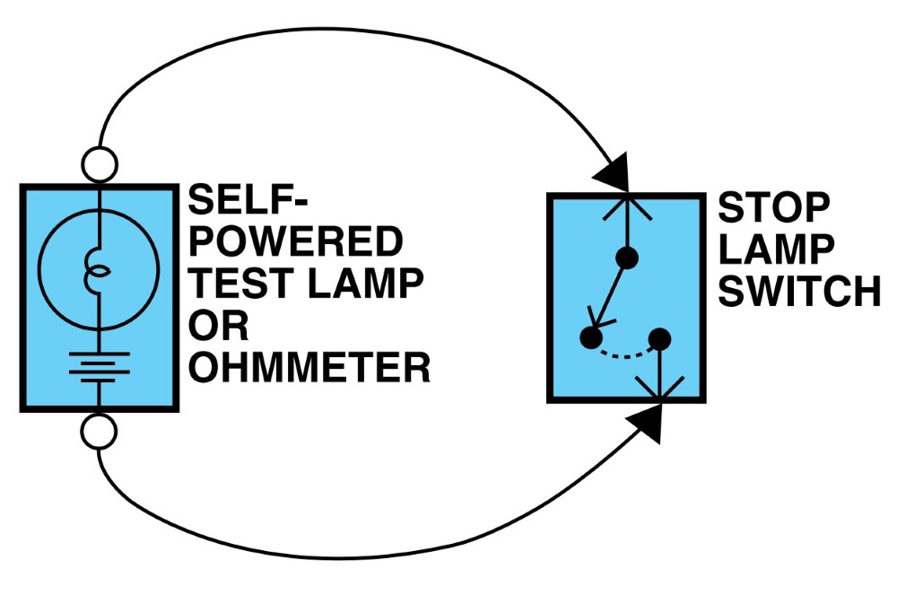
2. Testing for continuity.
A. Disconnect the battery negative terminal.
B. Connect one lead of a self-powered test lamp or ohmmeter to one end of the part of the circuit you wish to test. If you are using an ohmmeter, hold the leads together and adjust the ohmmeter to read zero ohms.
C. Connect the other lead to the other end.
D. If the self-power test lamp glows, there is continuity. If you are using an ohmmeter, low or zero resistance means good continuity.
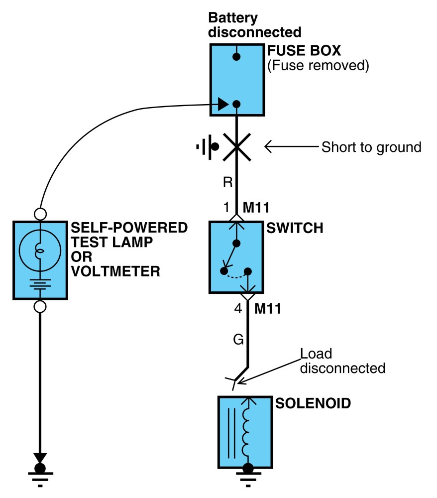
3. Testing for short to ground.
A. Disconnect the battery negative terminal.
B. Connect one lead of a self-powered test lamp or an ohmmeter to the fuse terminal on the load side.
C. Connect the other lead to a ground.
D. Beginning near the fuse block move the harness from side to side. Continue this proceedure(about six inches apart) while watching the self-powered test lamp or ohmmeter.
E. When the self-powered test lamp glows, or ohmmeter registers, there is a short to a ground in the wiring near that point.
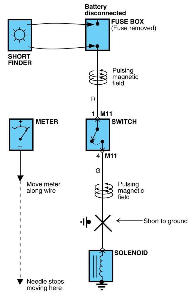
4. Testing for a short with a short finder.
A. Remove the blown fuse. Leave the battery connected.
B. Connect the short finder across the fuse terminals.
C. Close all switches in series in the circuit that is being testing.
D. Turn on the short circuit locator. It sends pulses of current to the short. This creates a pulsing magnetic field around the wiring between the fuse box and the short.
E. Beginning at the fuse box, slowly move the short finder along the circuit wiring. The meter will show current pulses through sheet metal and body trim. As long as the meter is between the fuse and the short, the needle will move with each current pulse. Once the meter is moved past the point of the short, the needle will stop moving. Check around this area to locate the cause of the short circuit.
Use the designated fuse only.
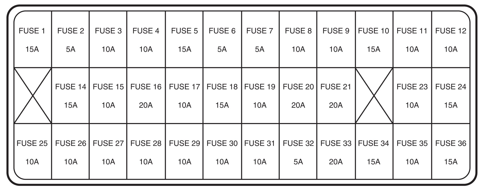
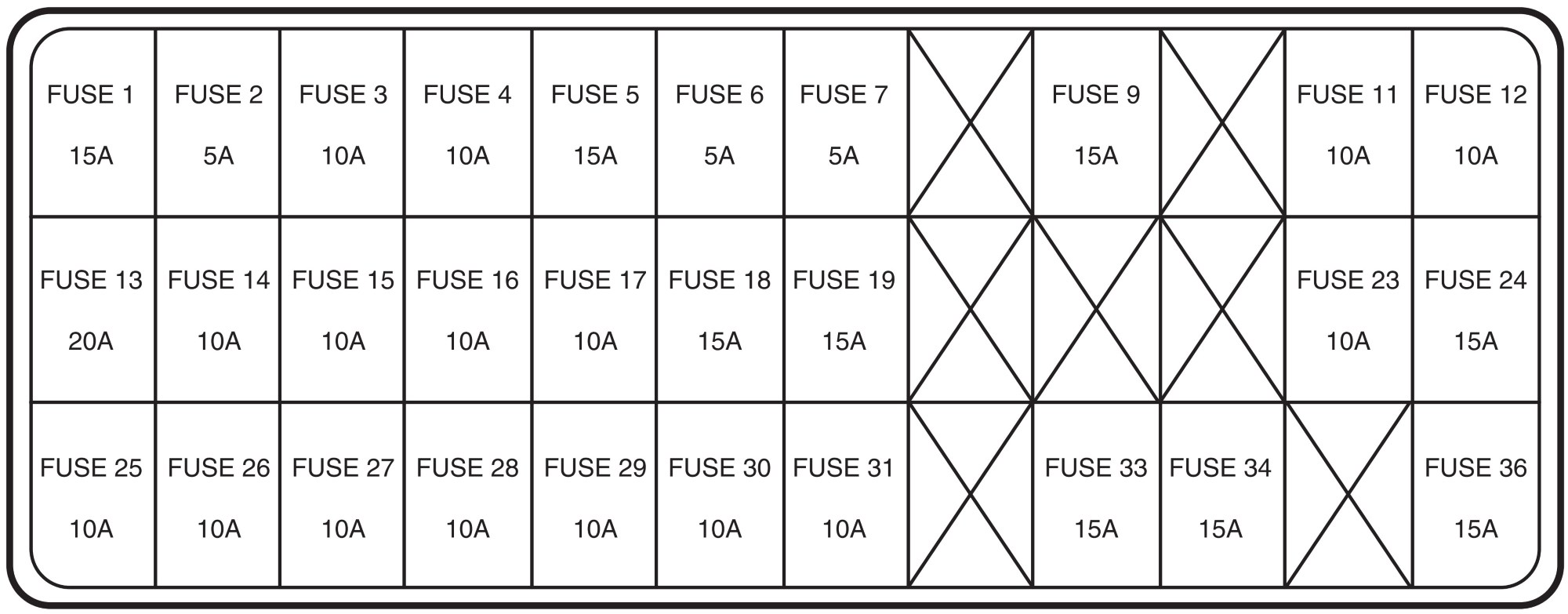
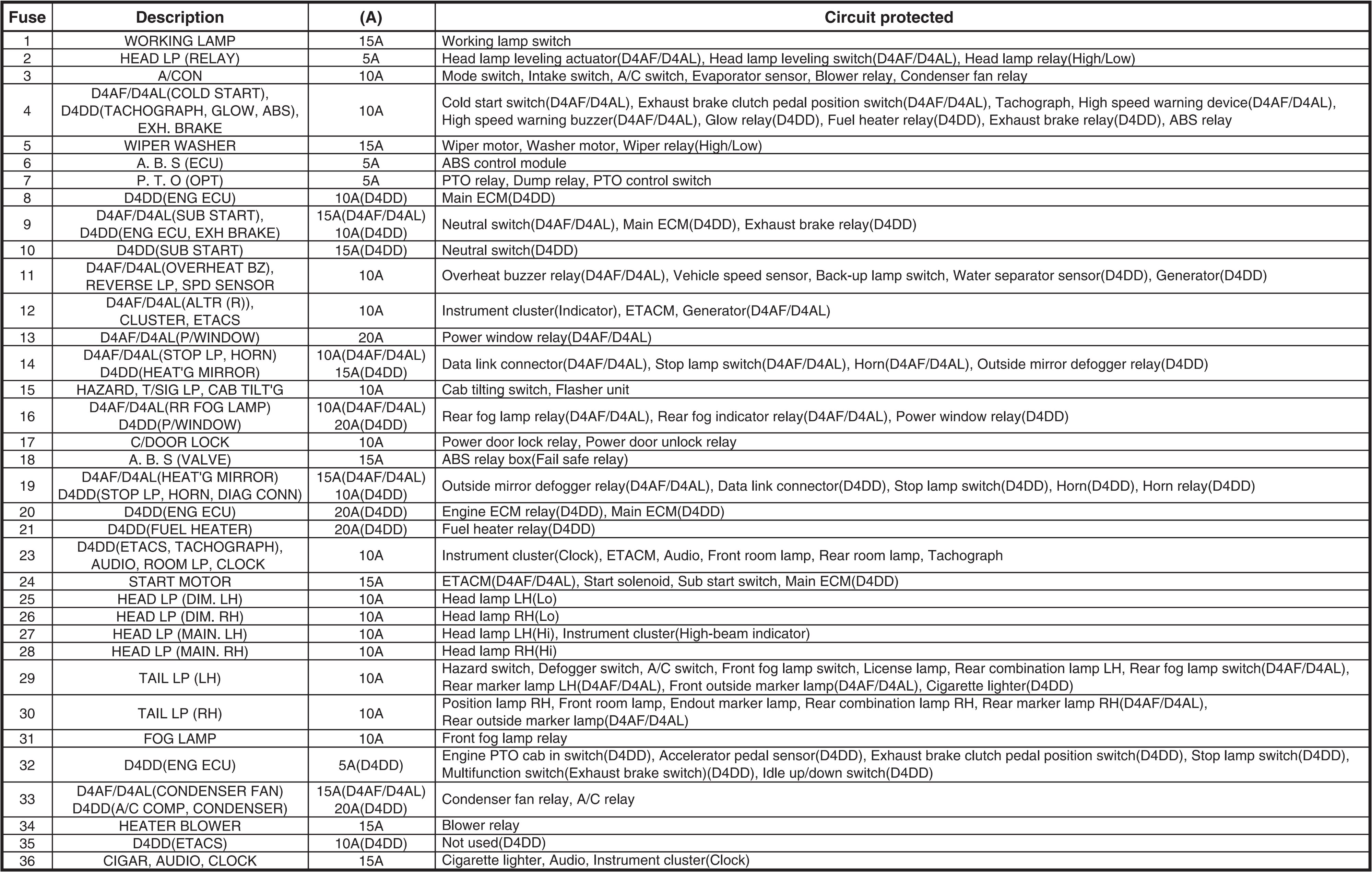
Fuse box.
D4DD.
D4AF/D4AL.
Circuit.
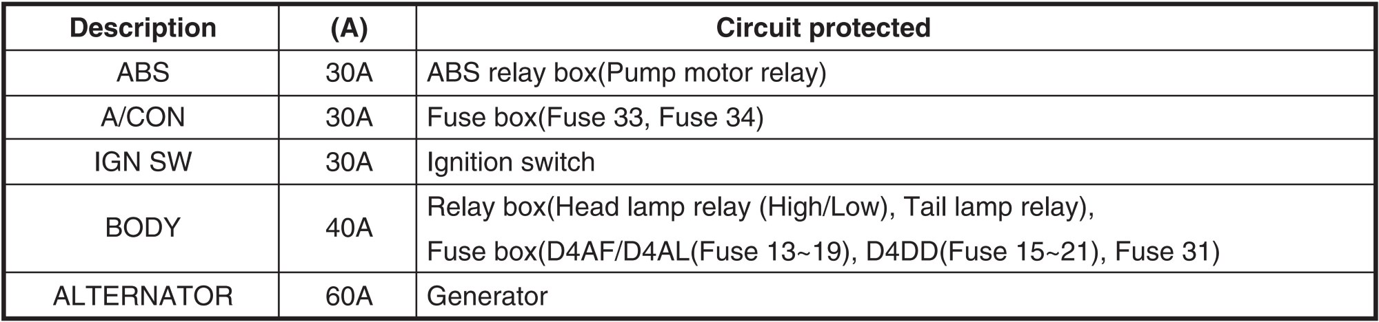
Fusible link box.
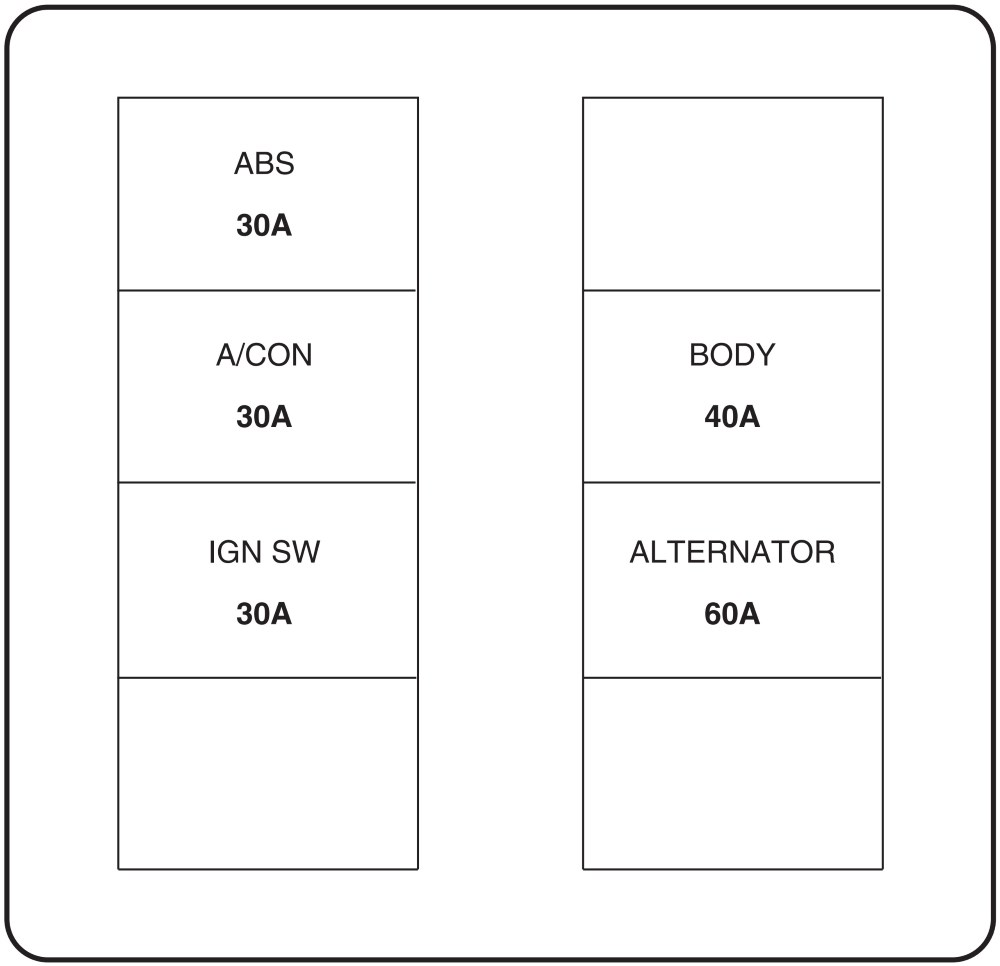
Circuit.
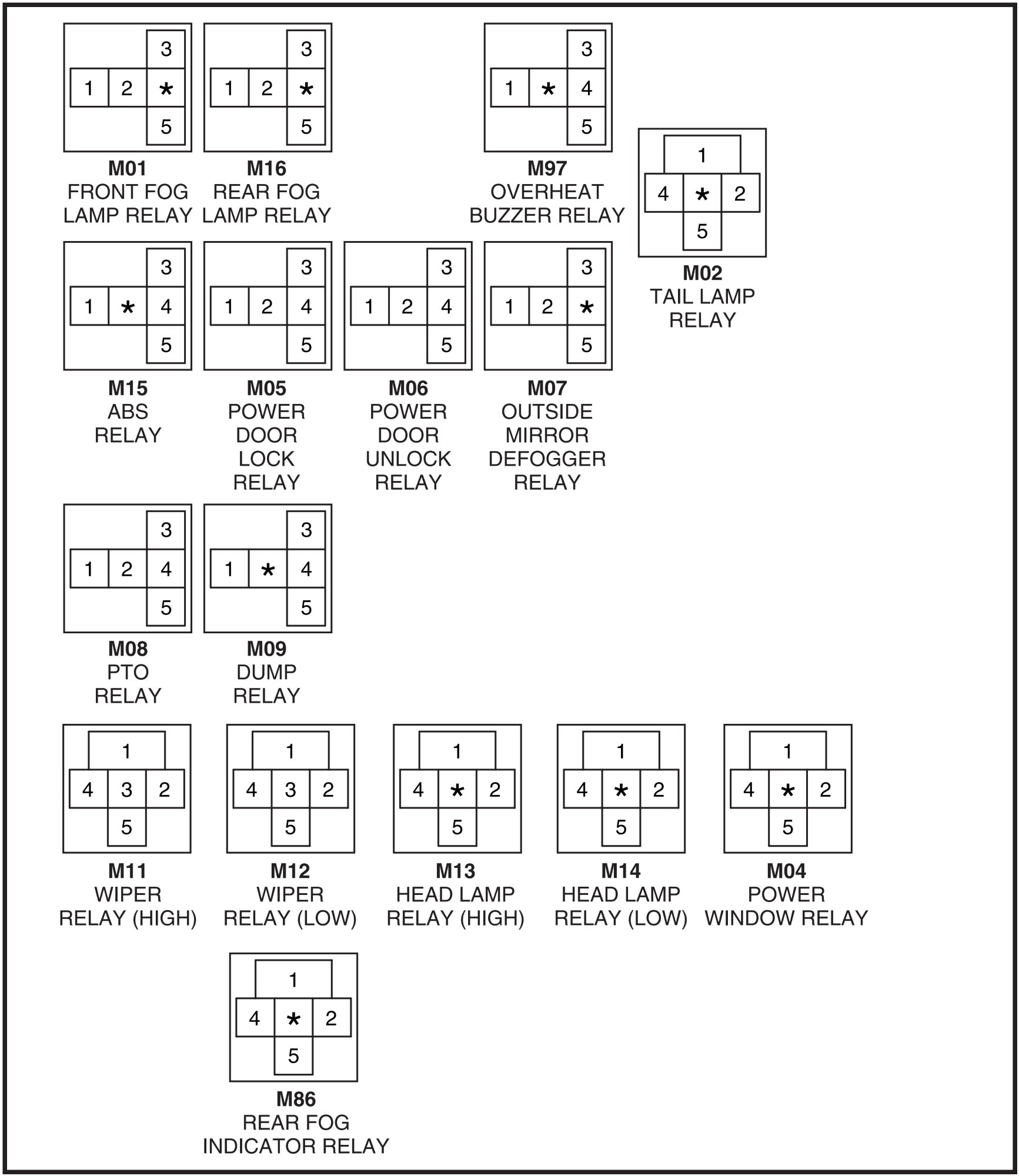
Relay box.
D4DD.
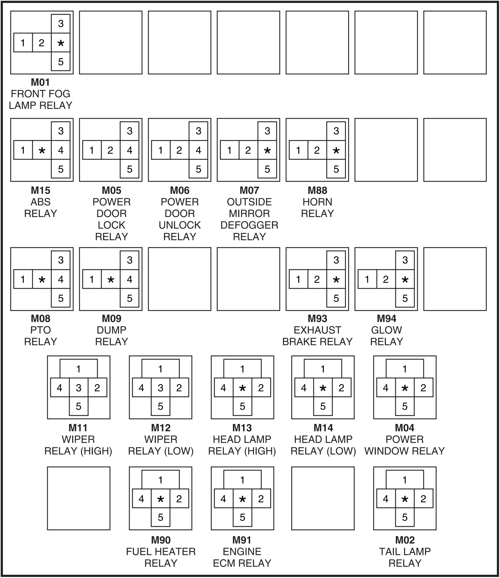
D4AF/D4AL.
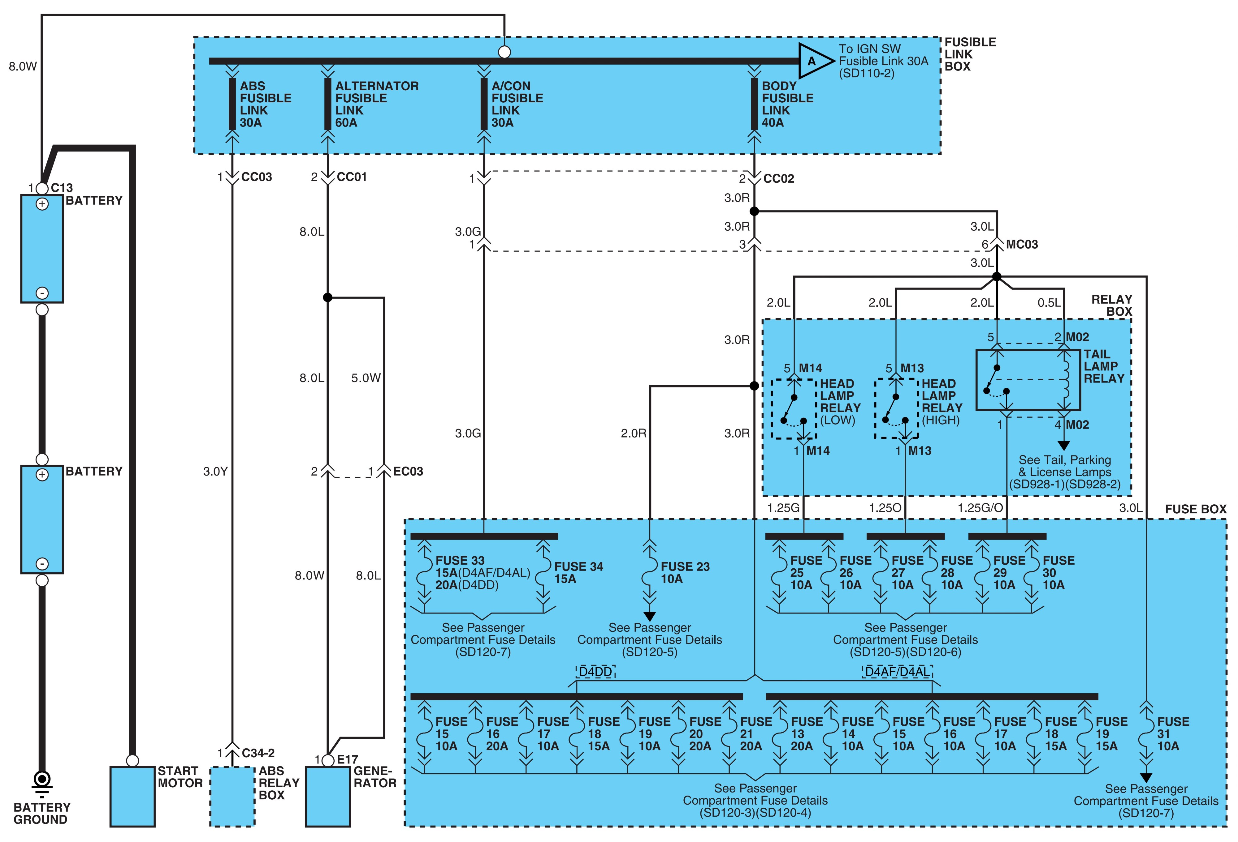
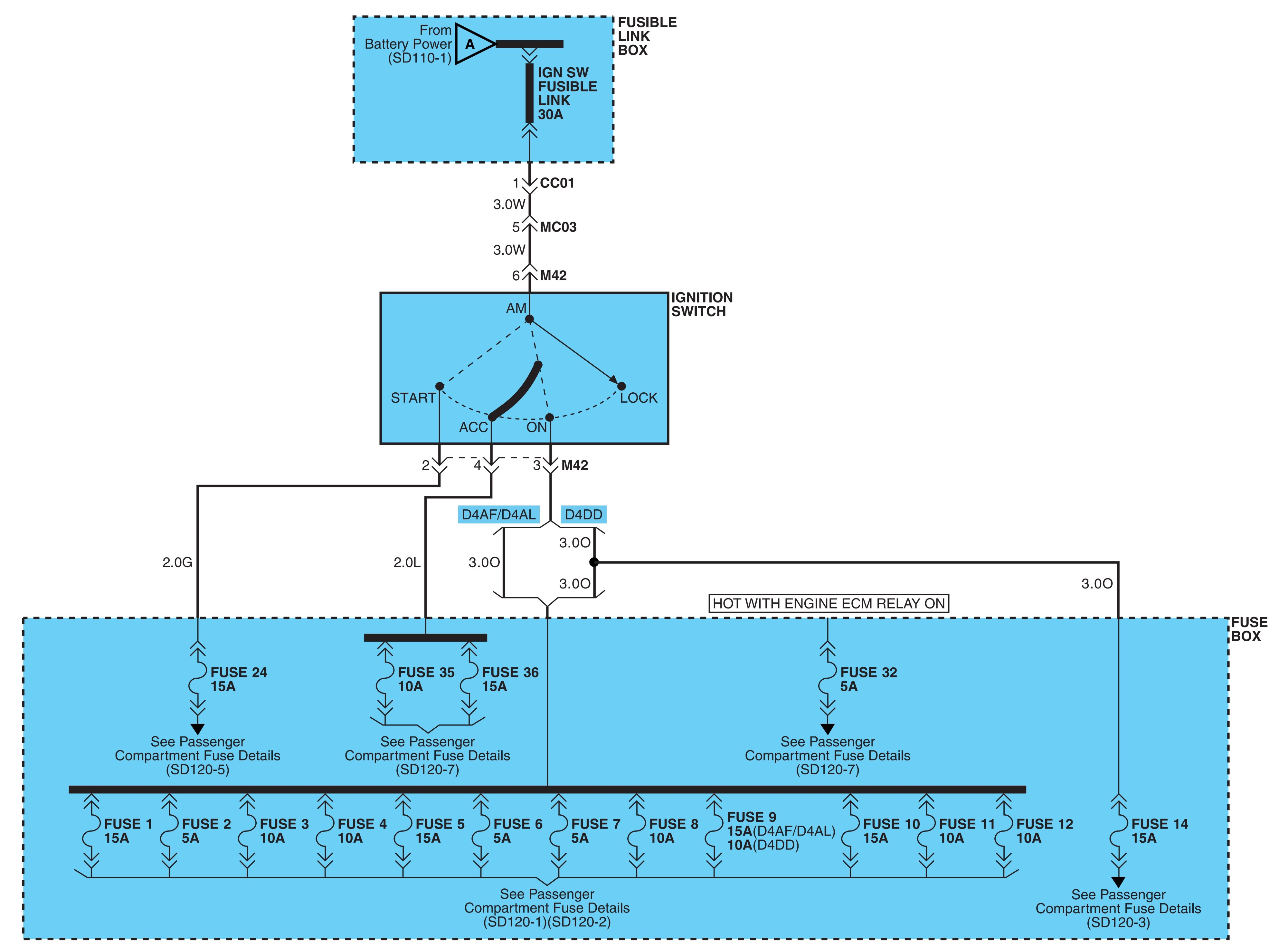
Passenger compartment fuse details.
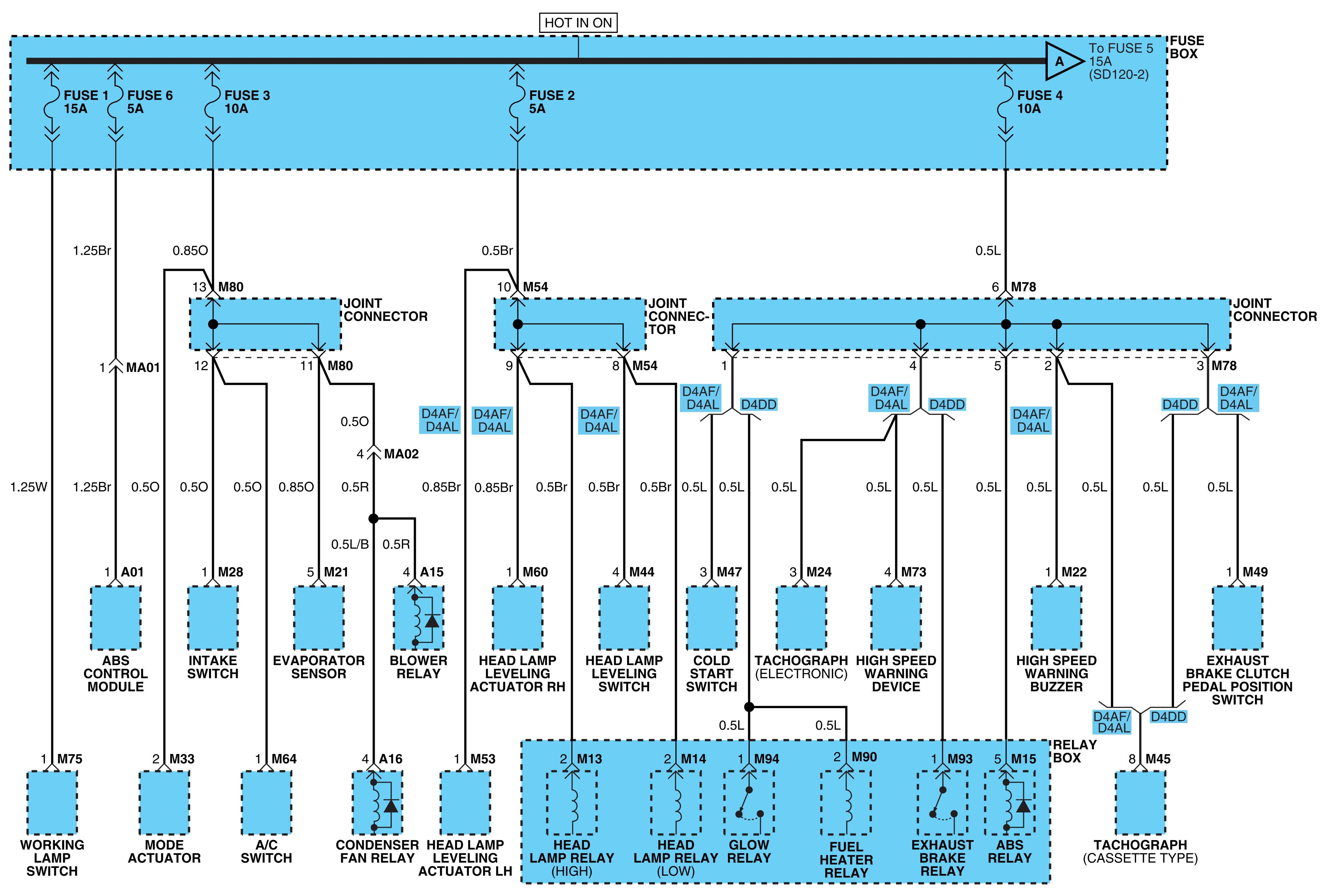
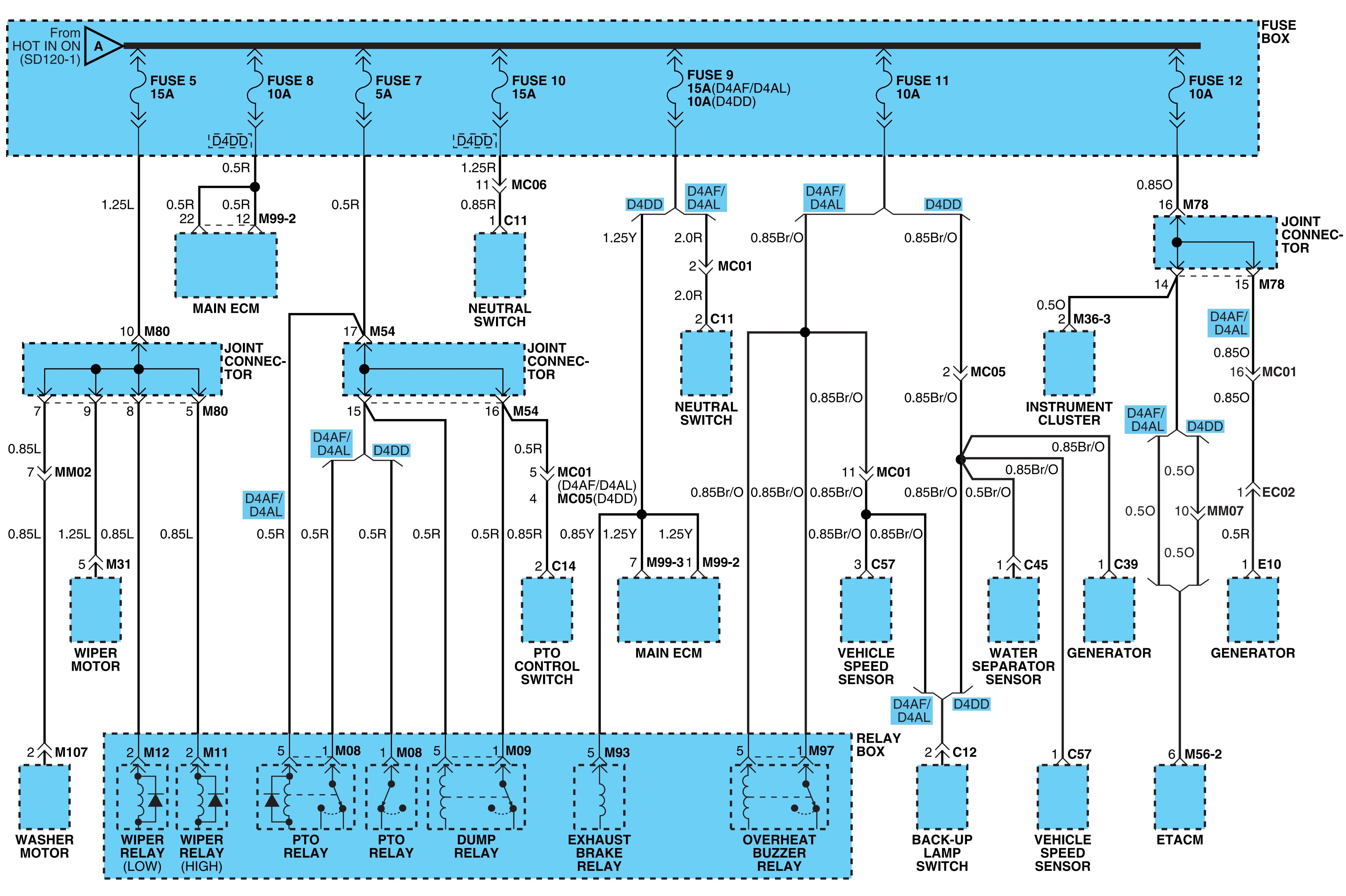
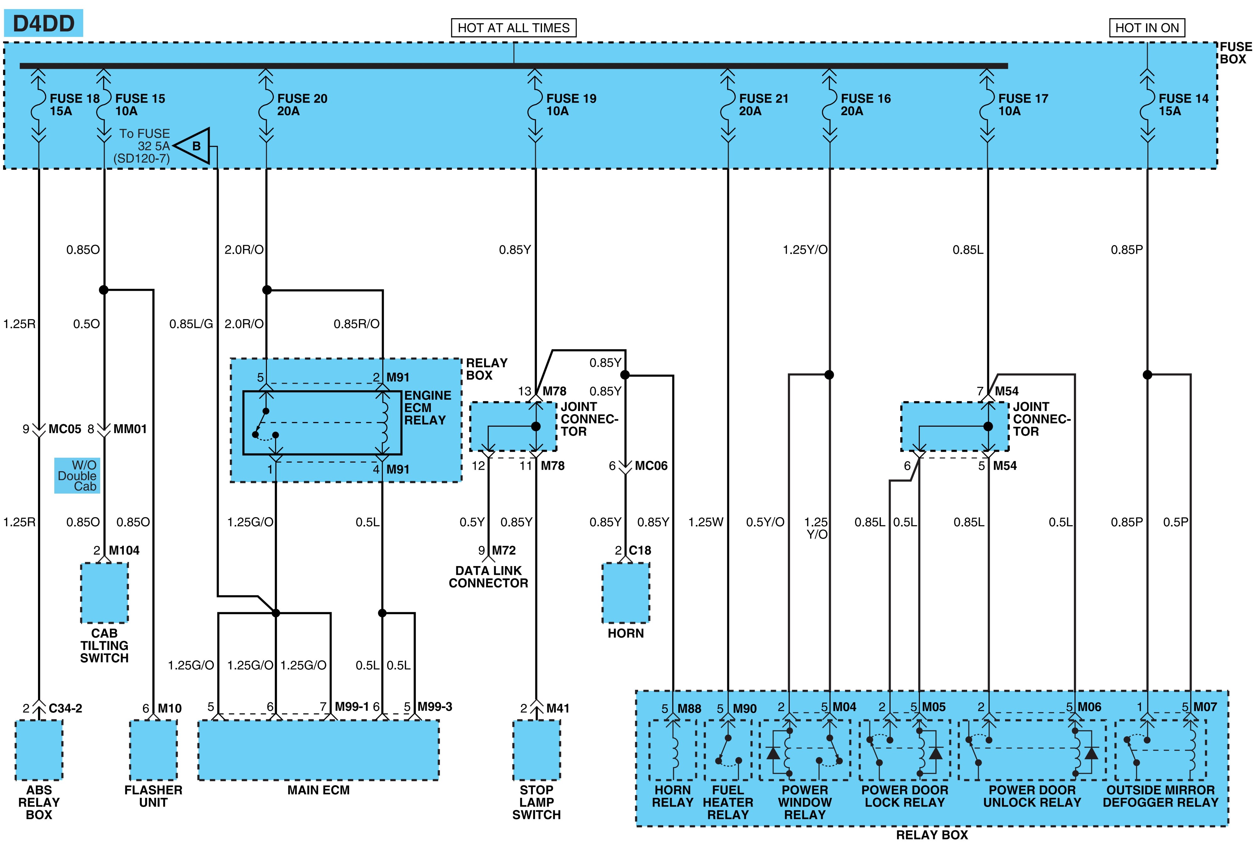
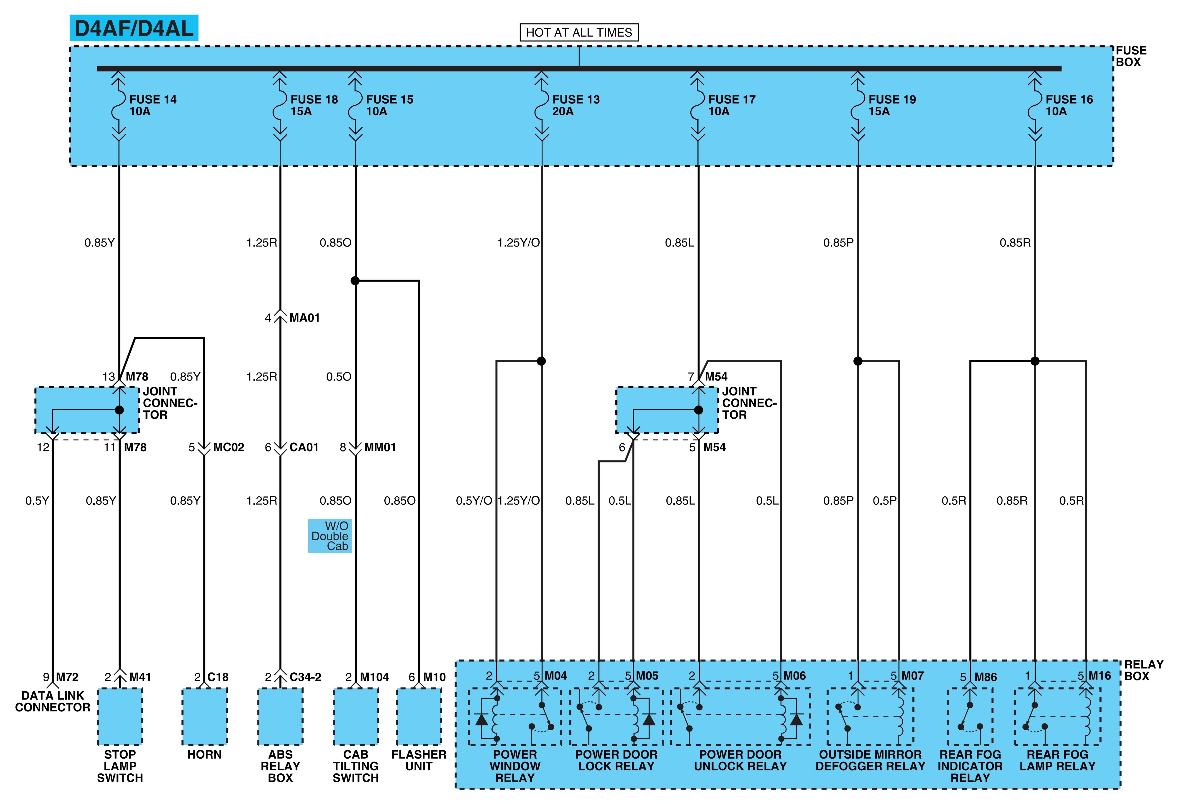
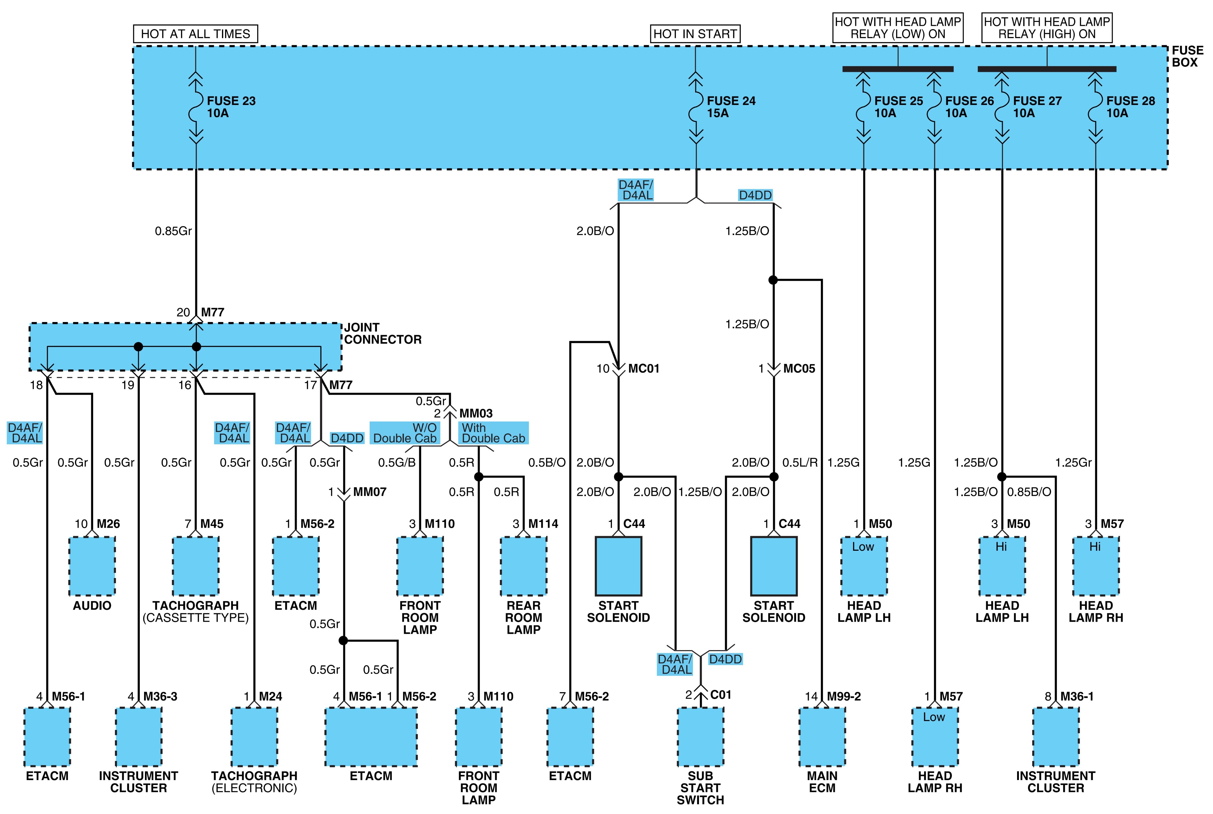
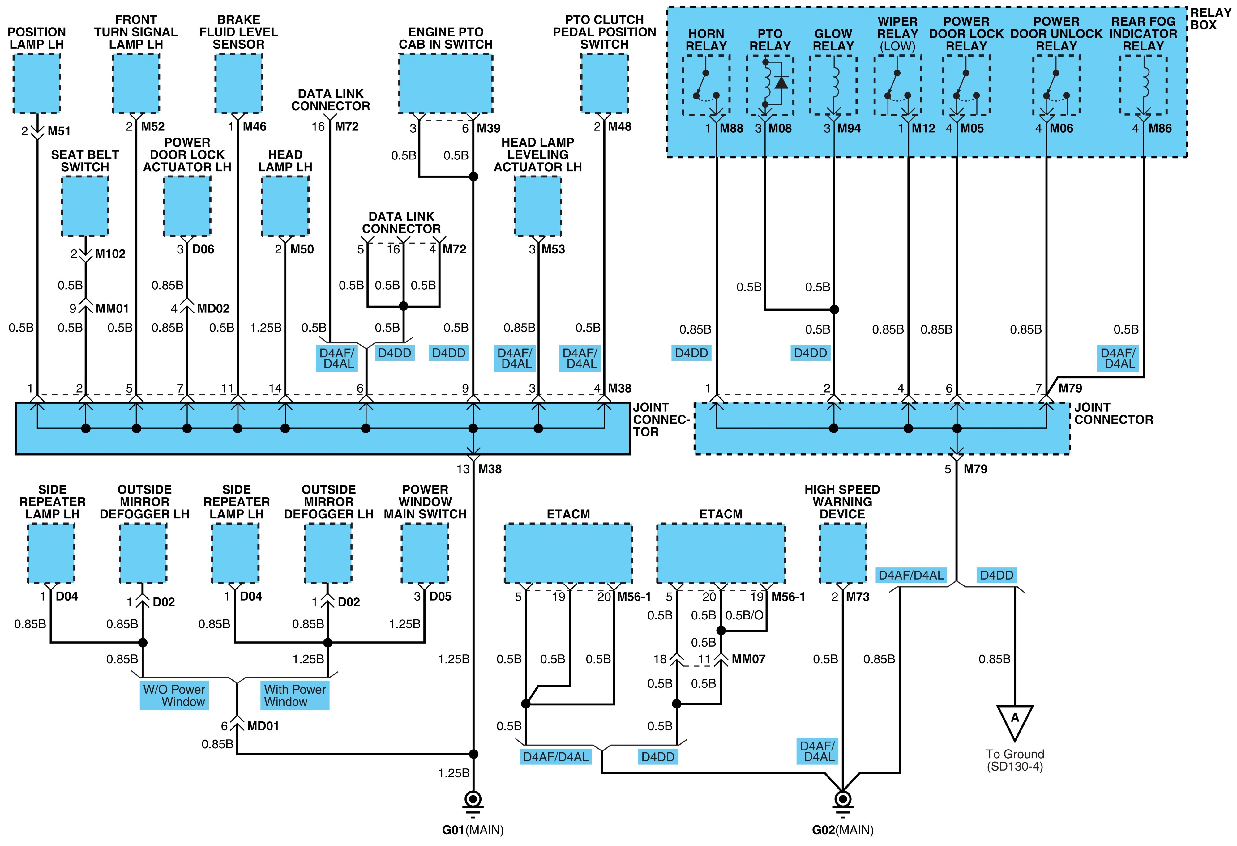
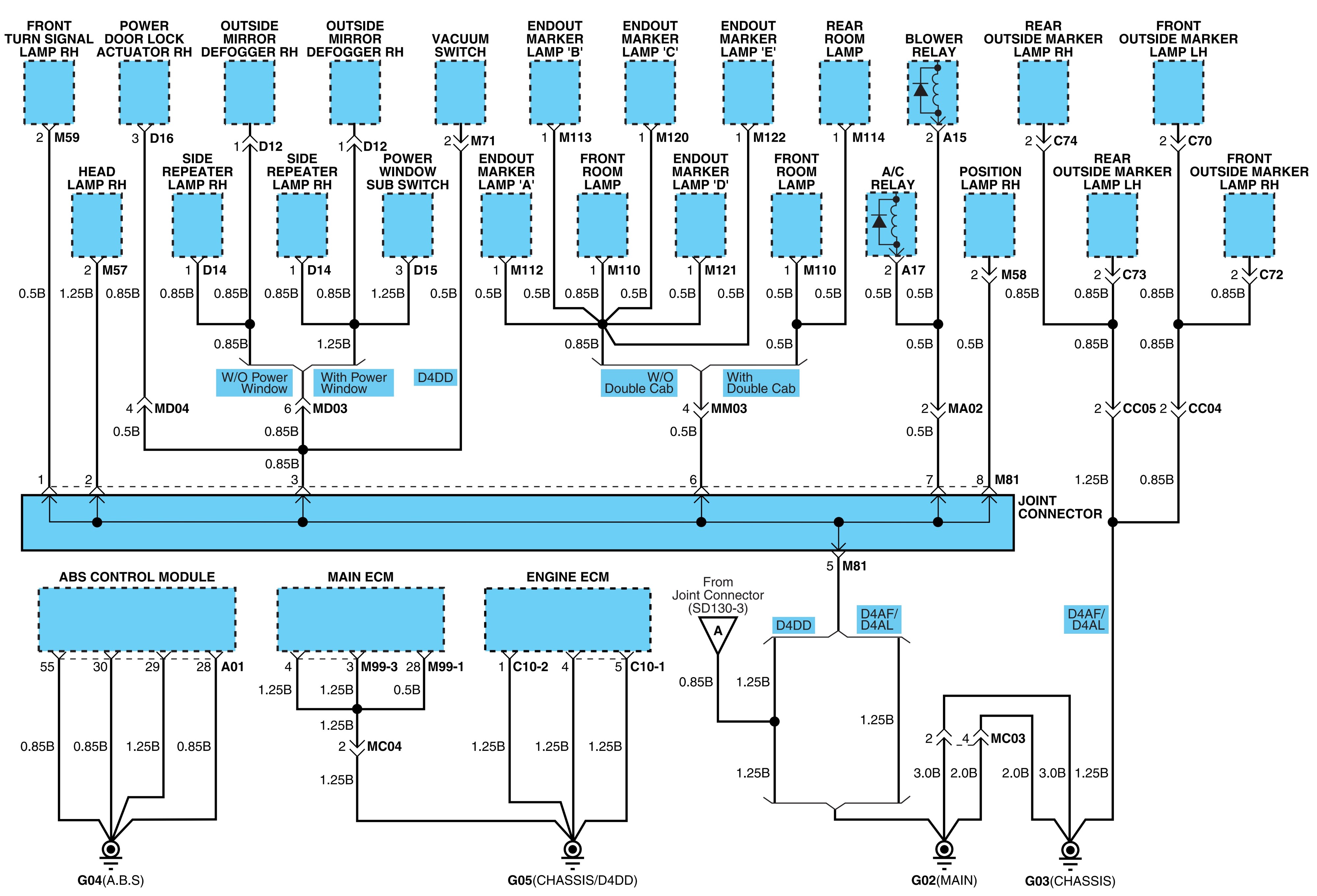
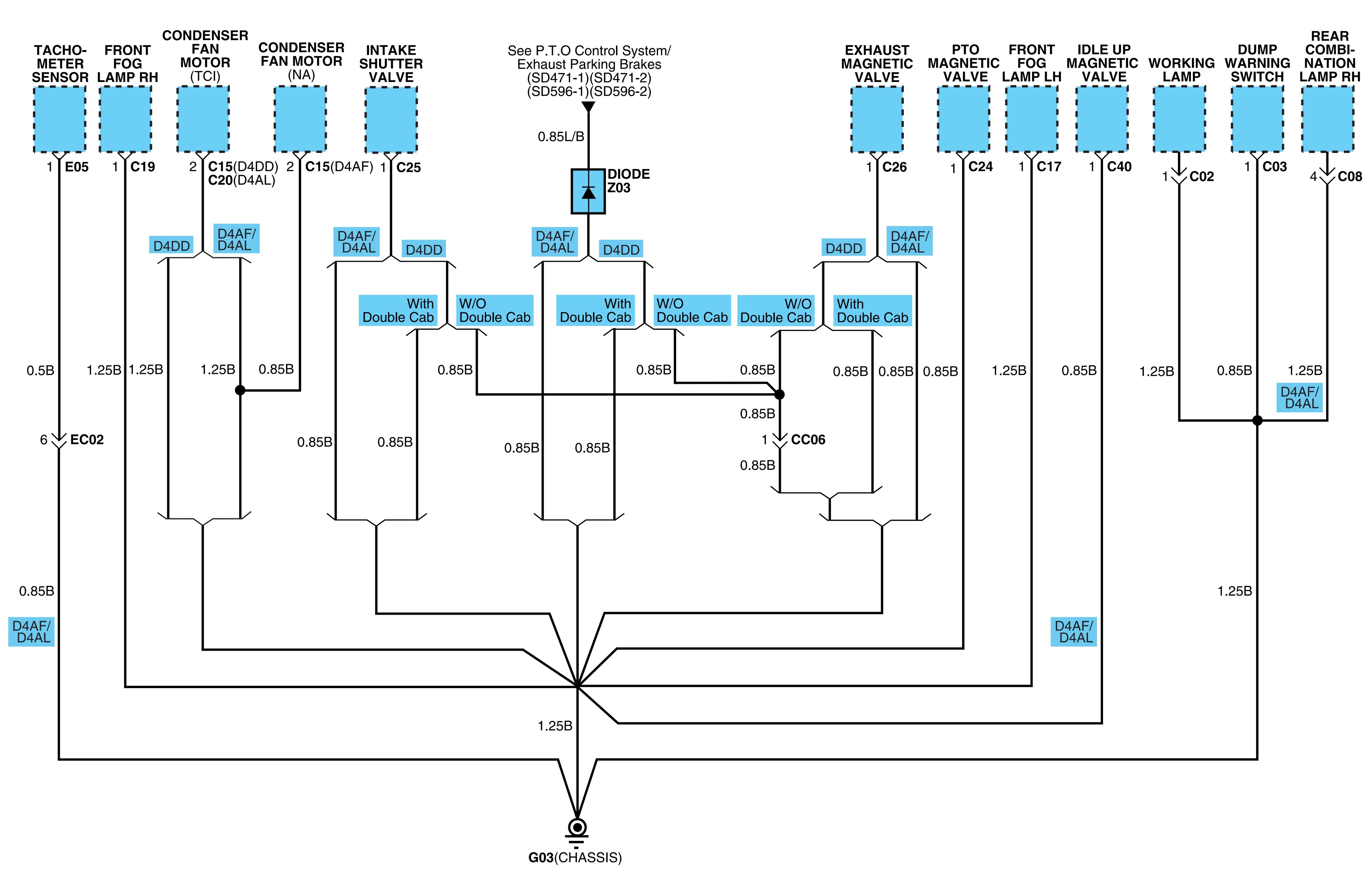
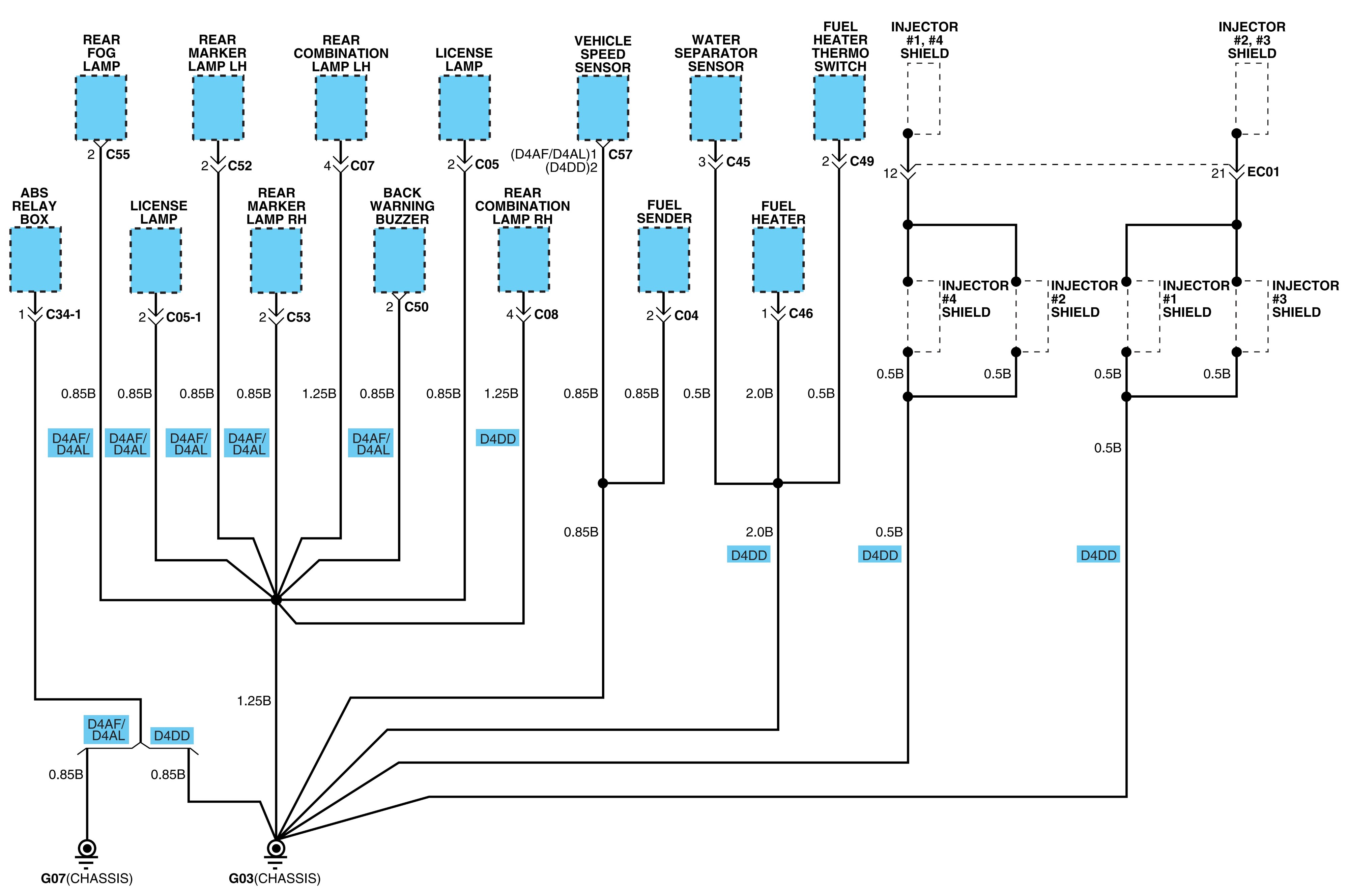
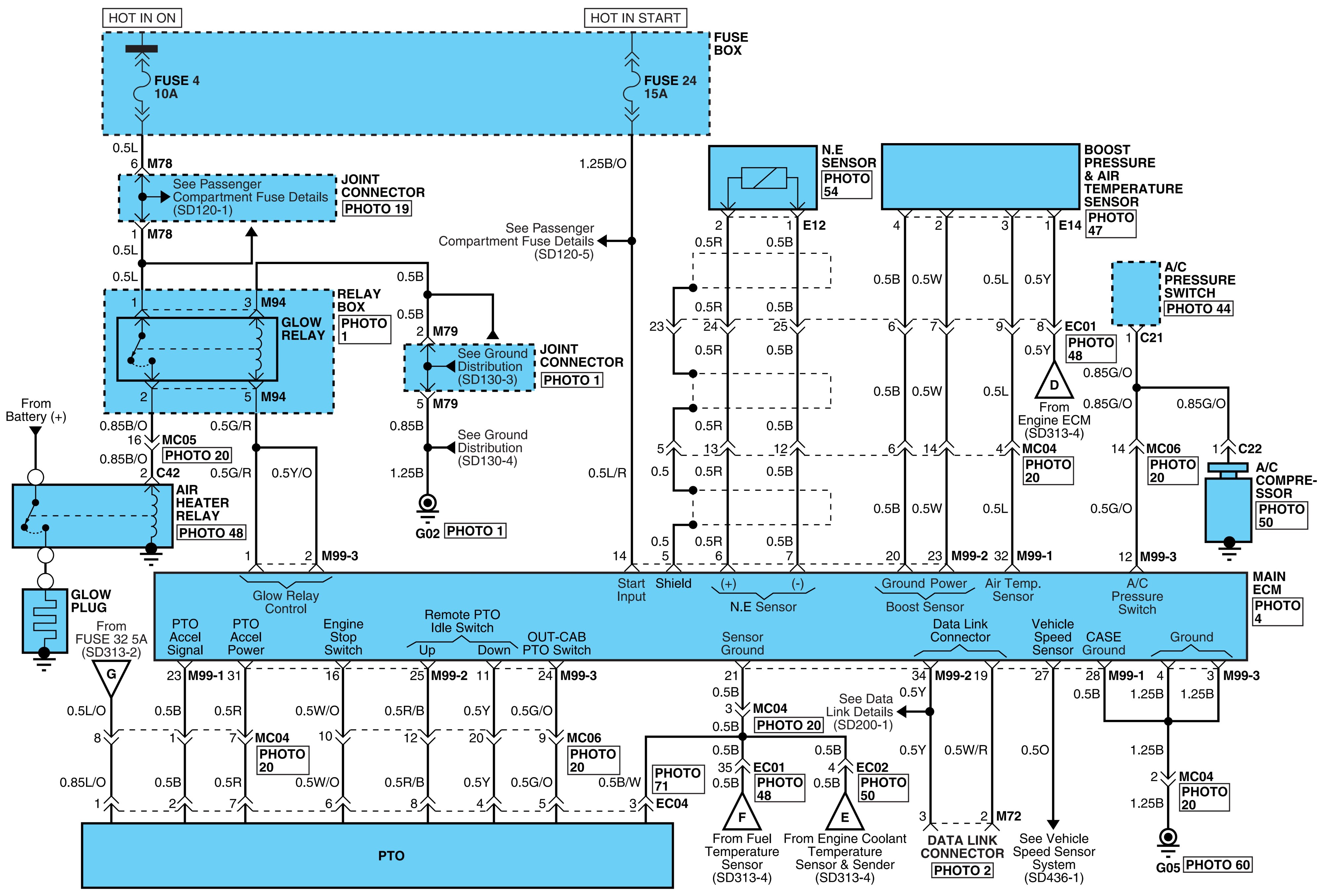
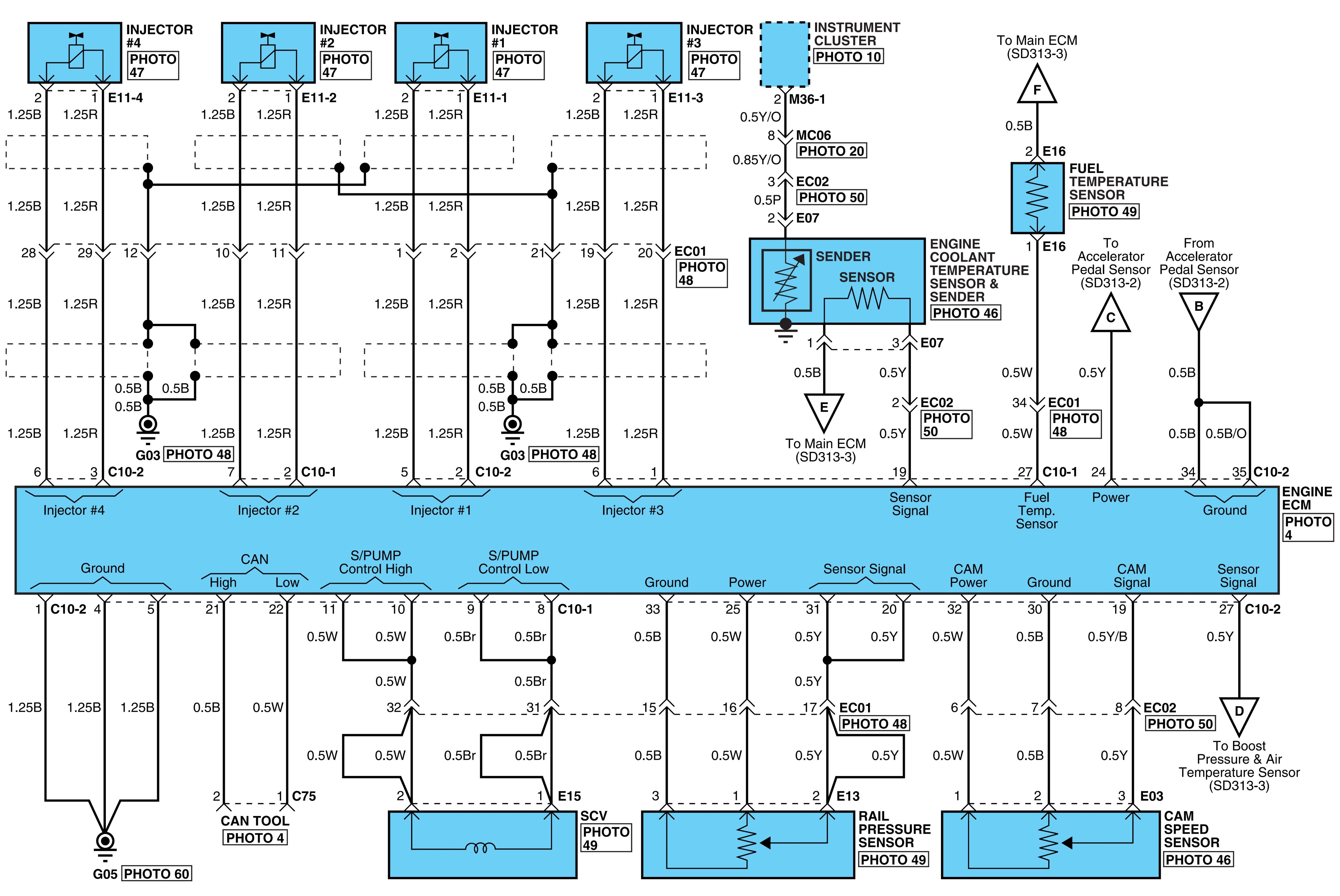
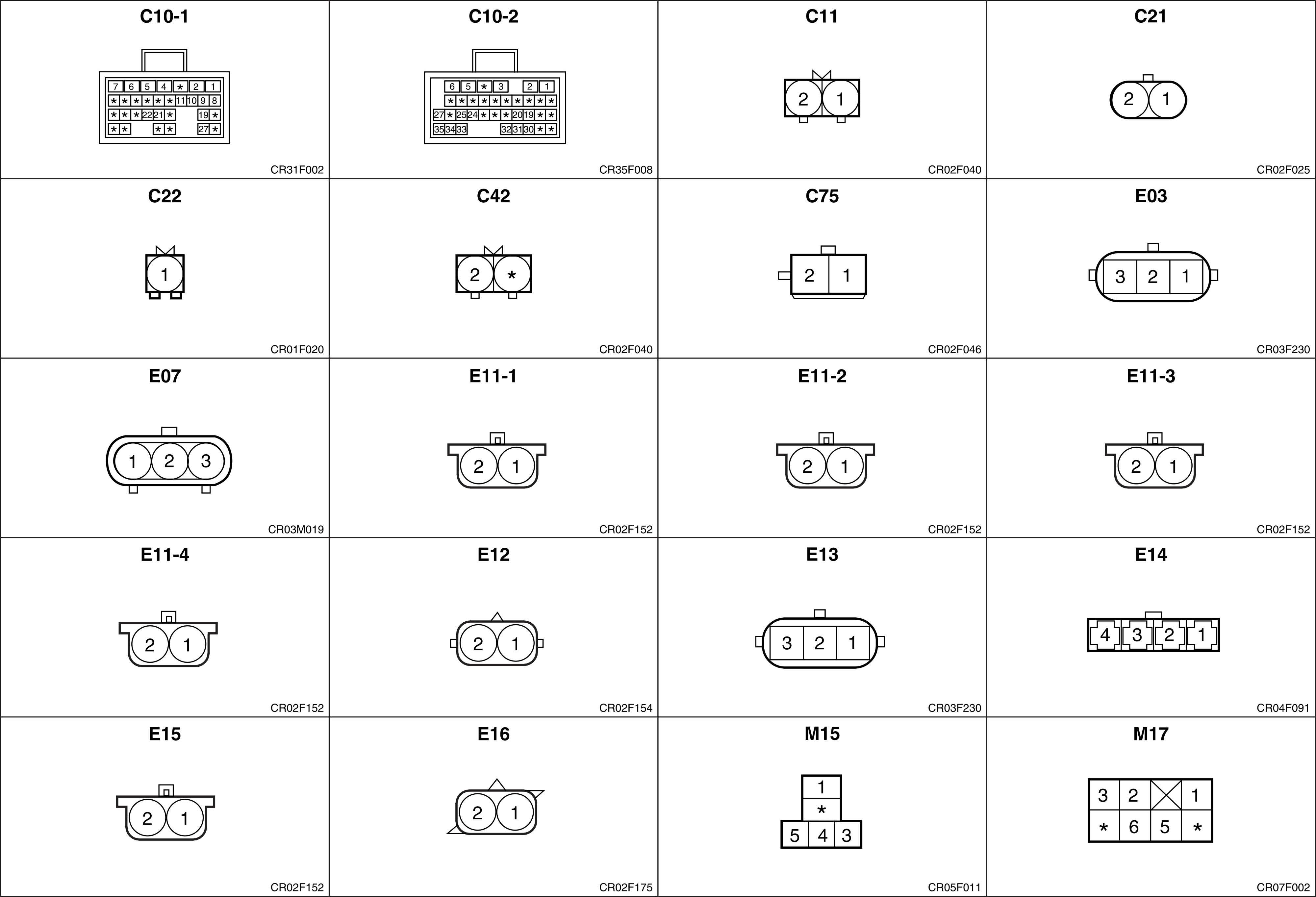
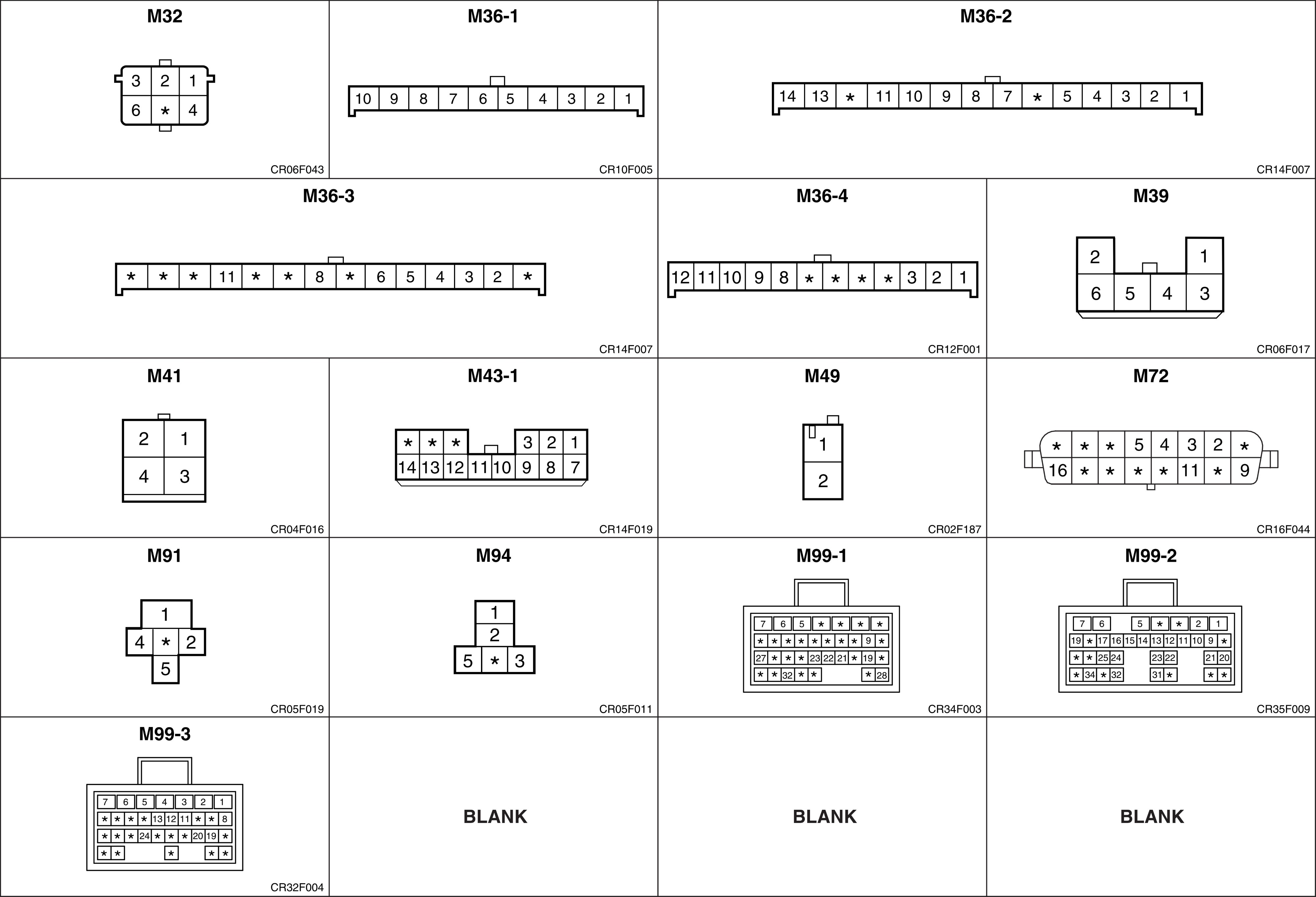
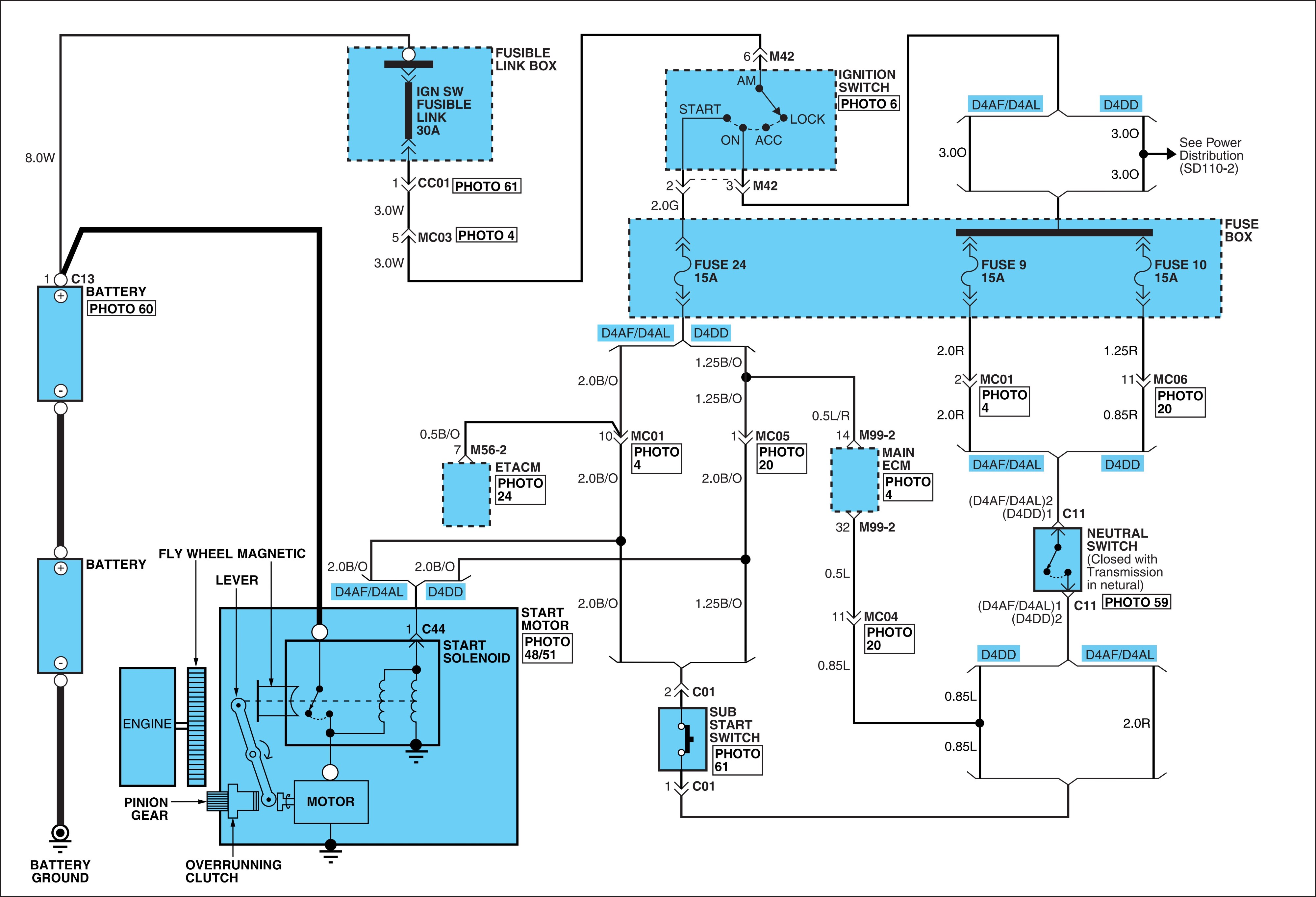
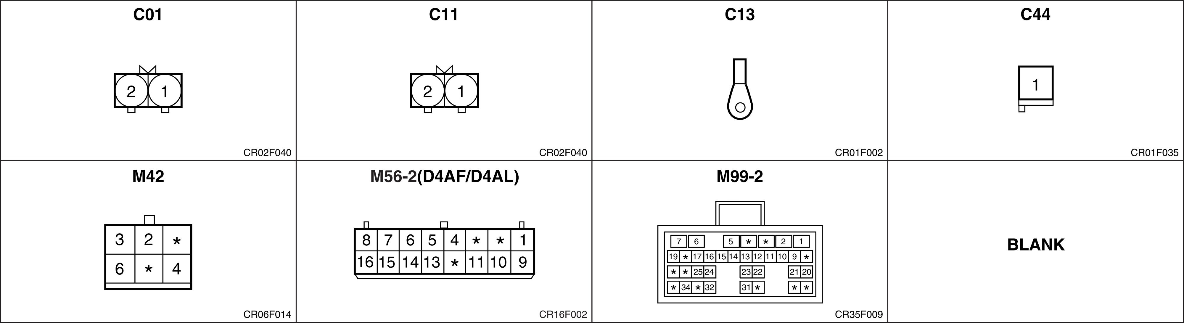
Fuel filter heating system (D4DD).

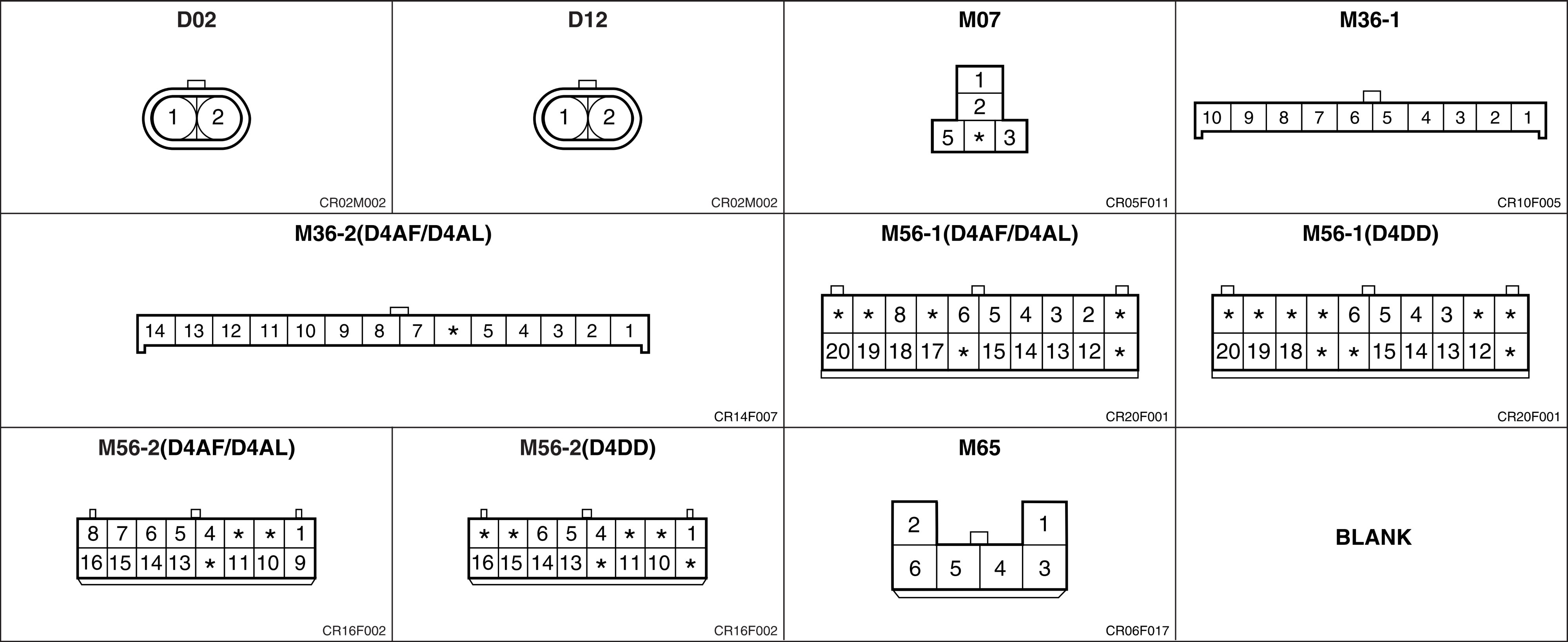
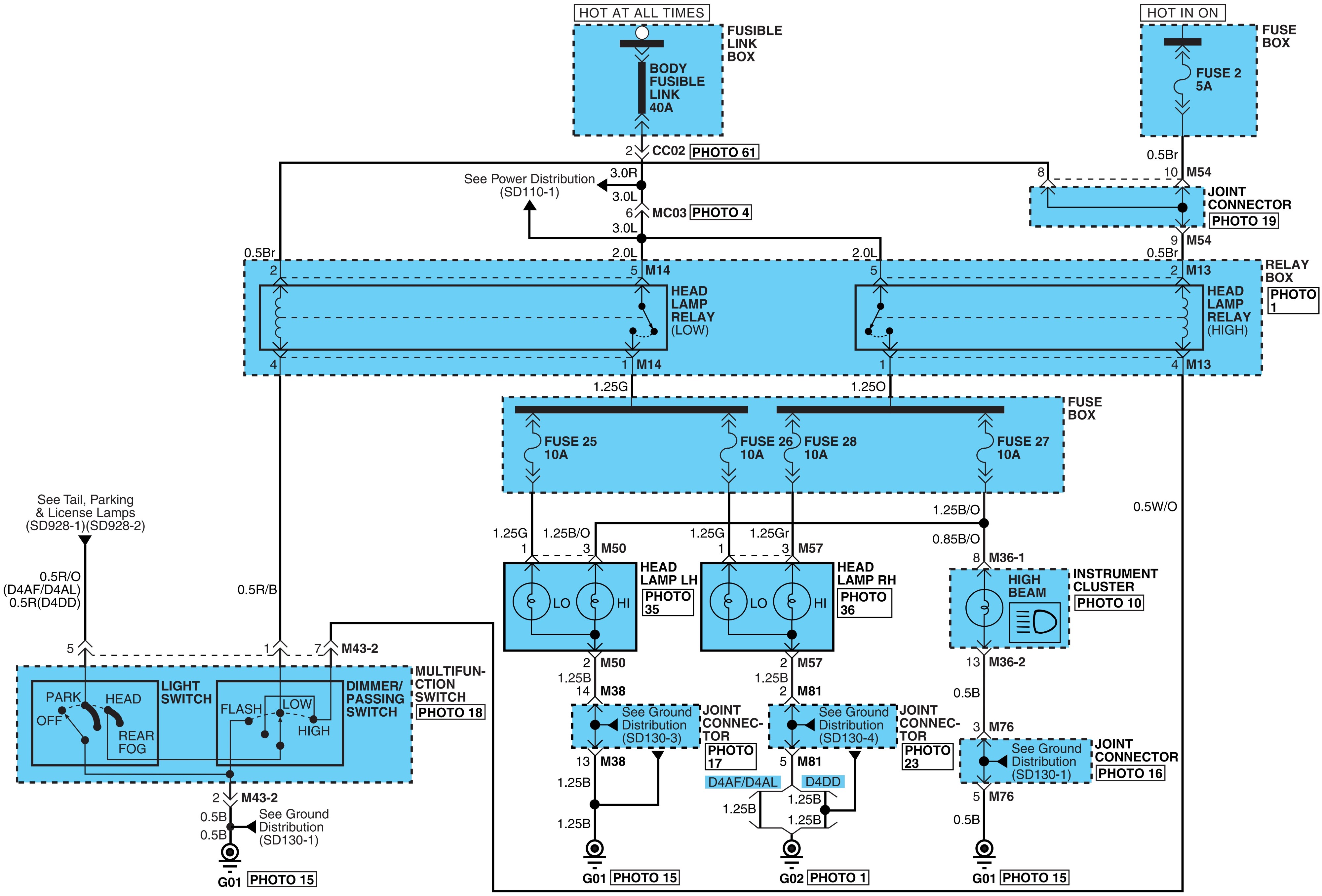
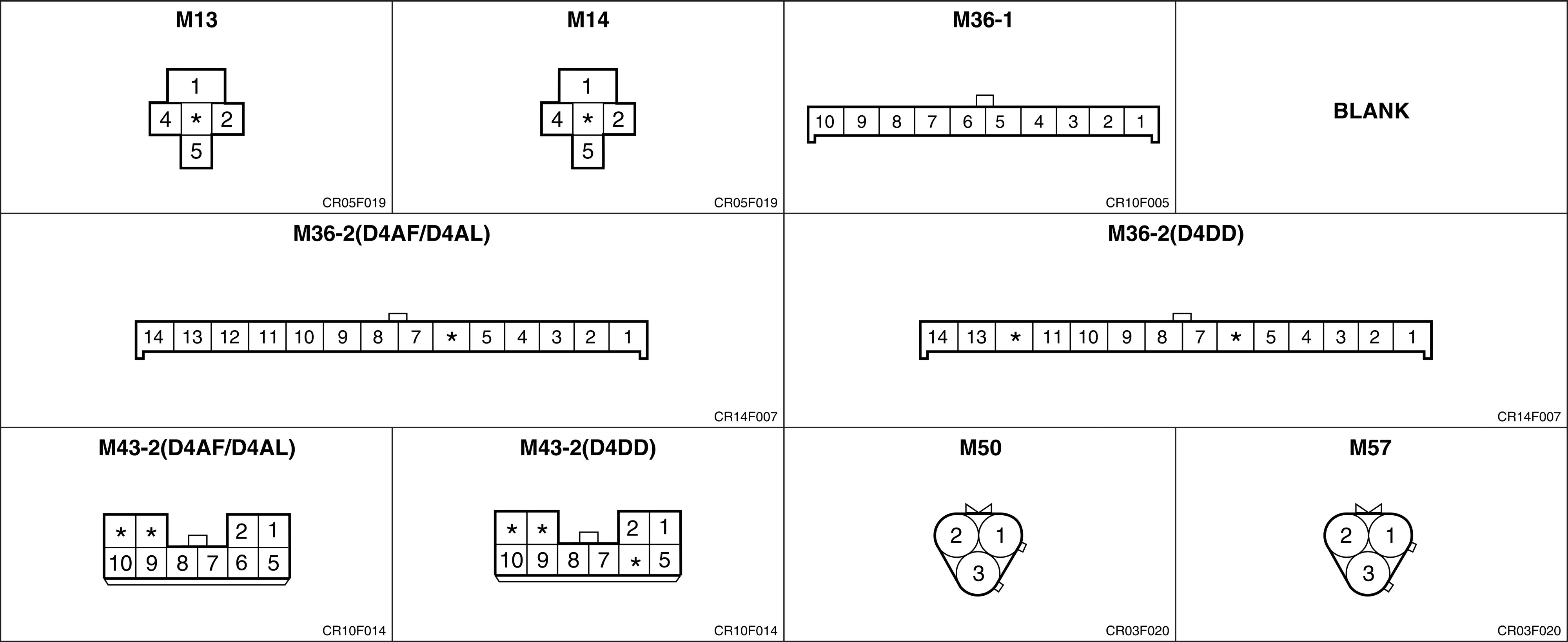
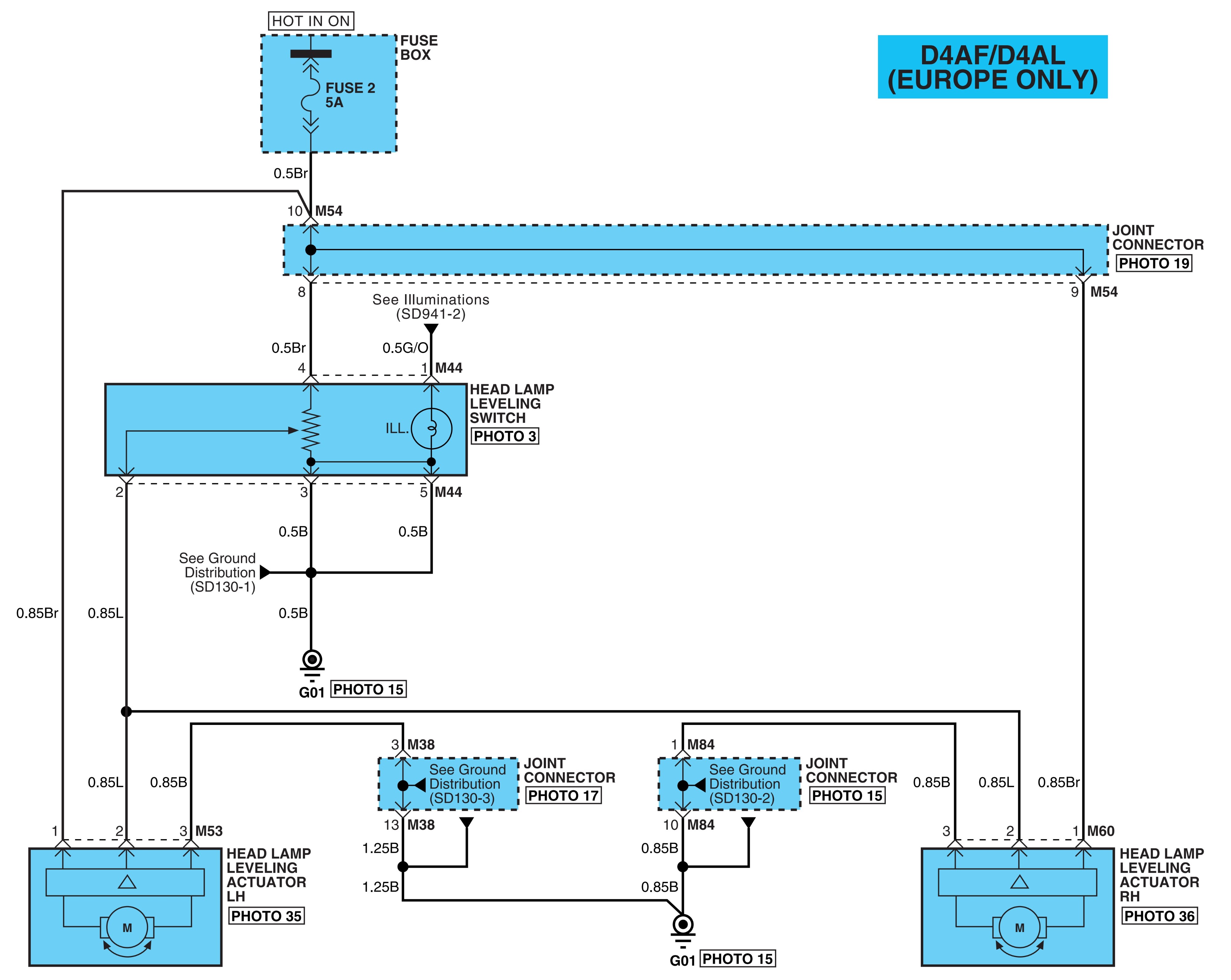

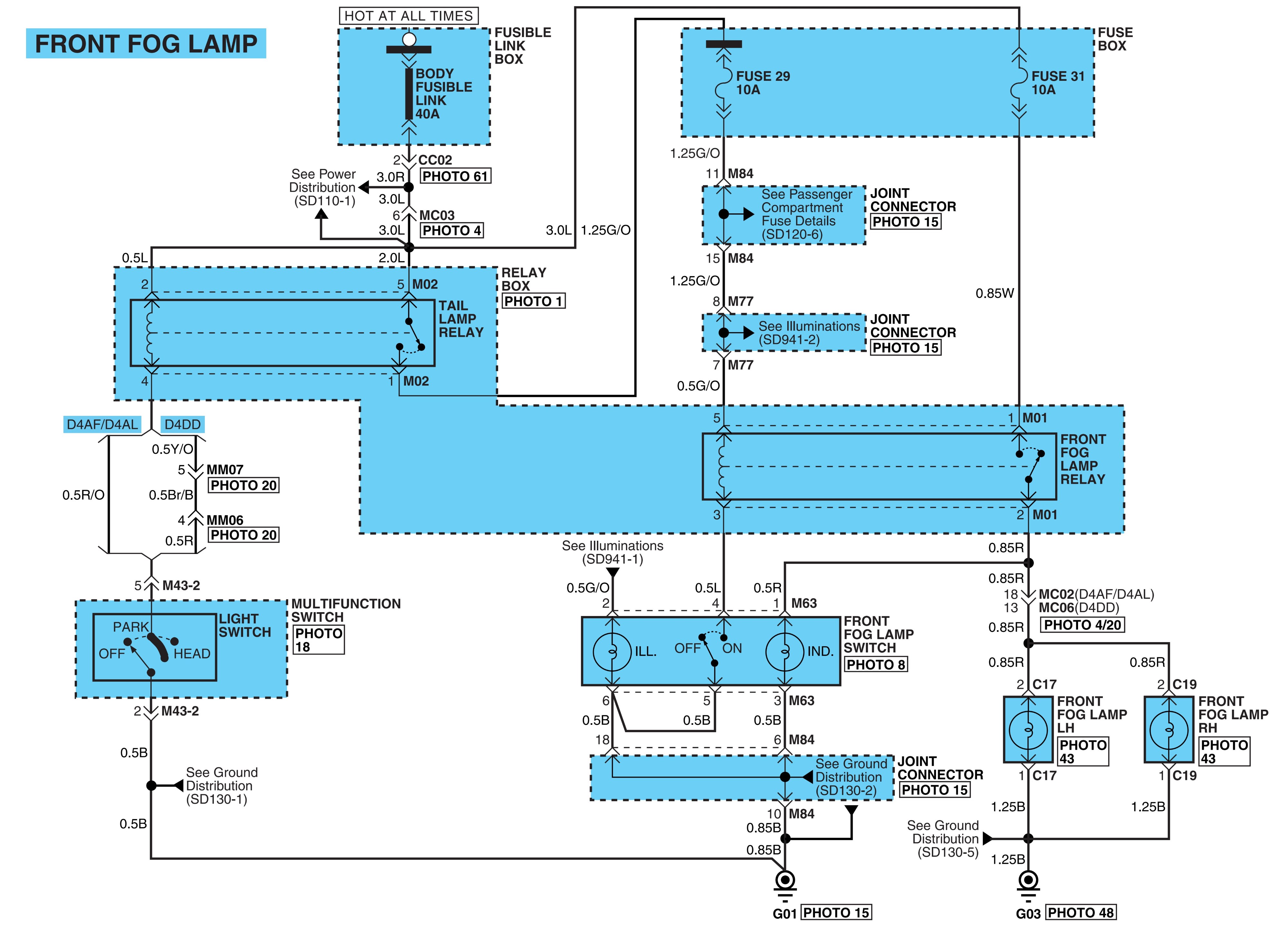
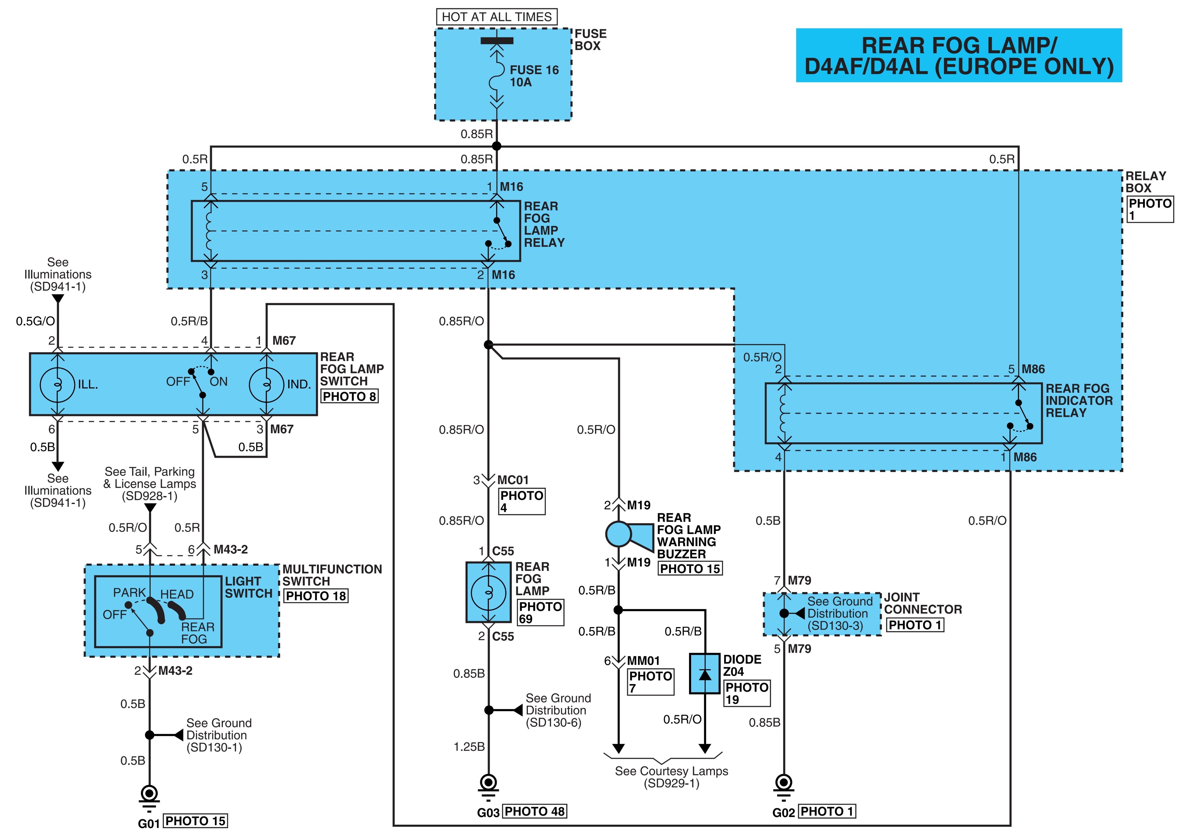
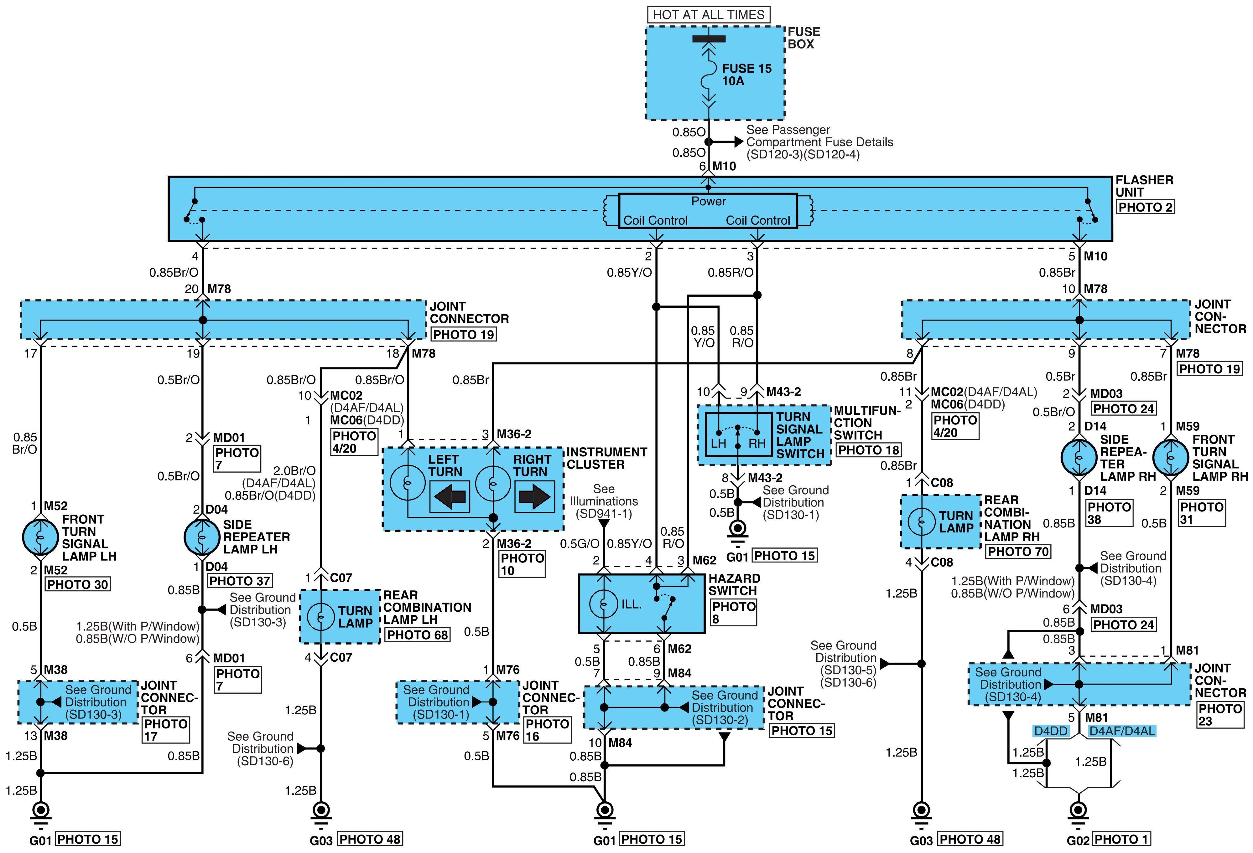

Tail, parking & license lamps.
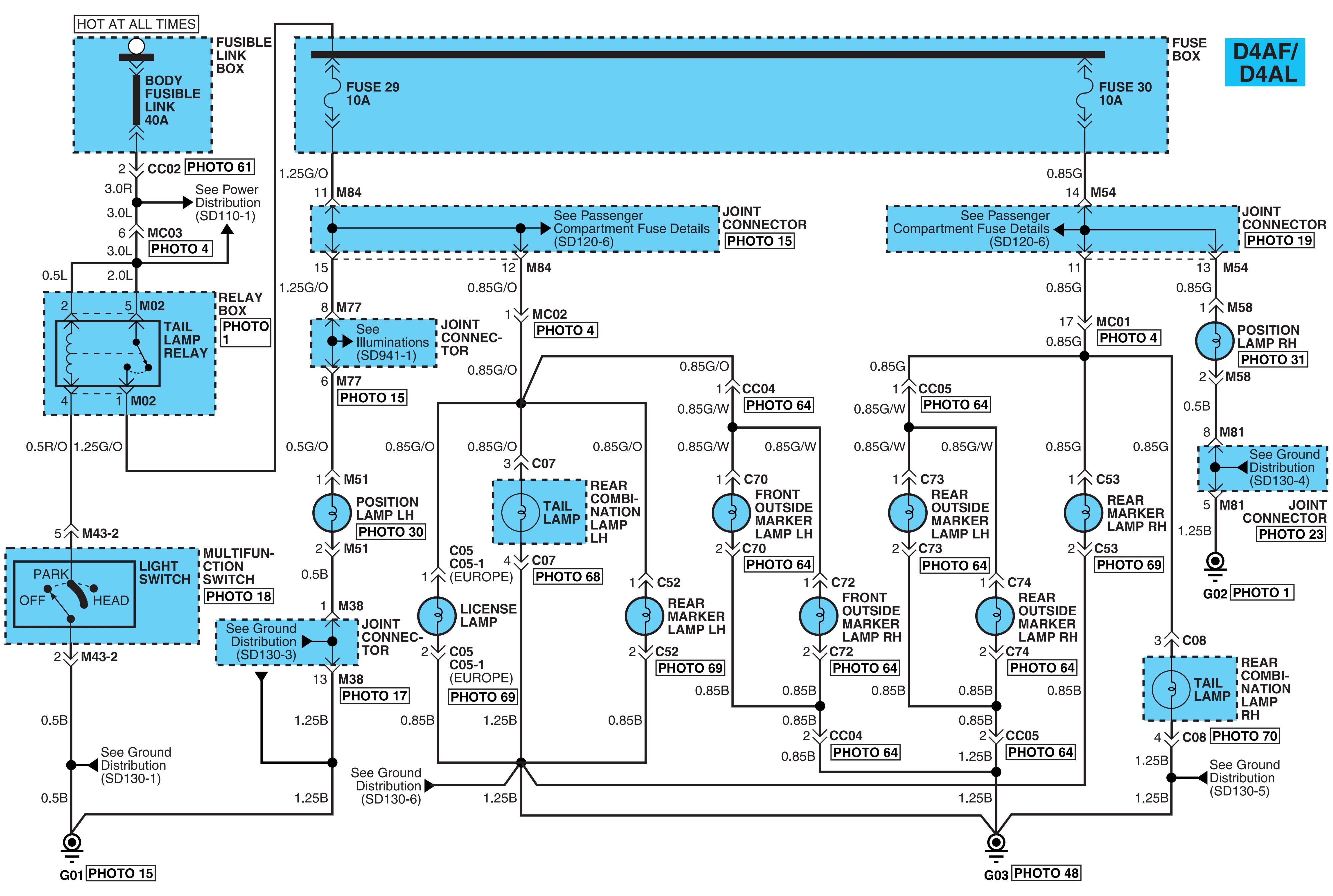
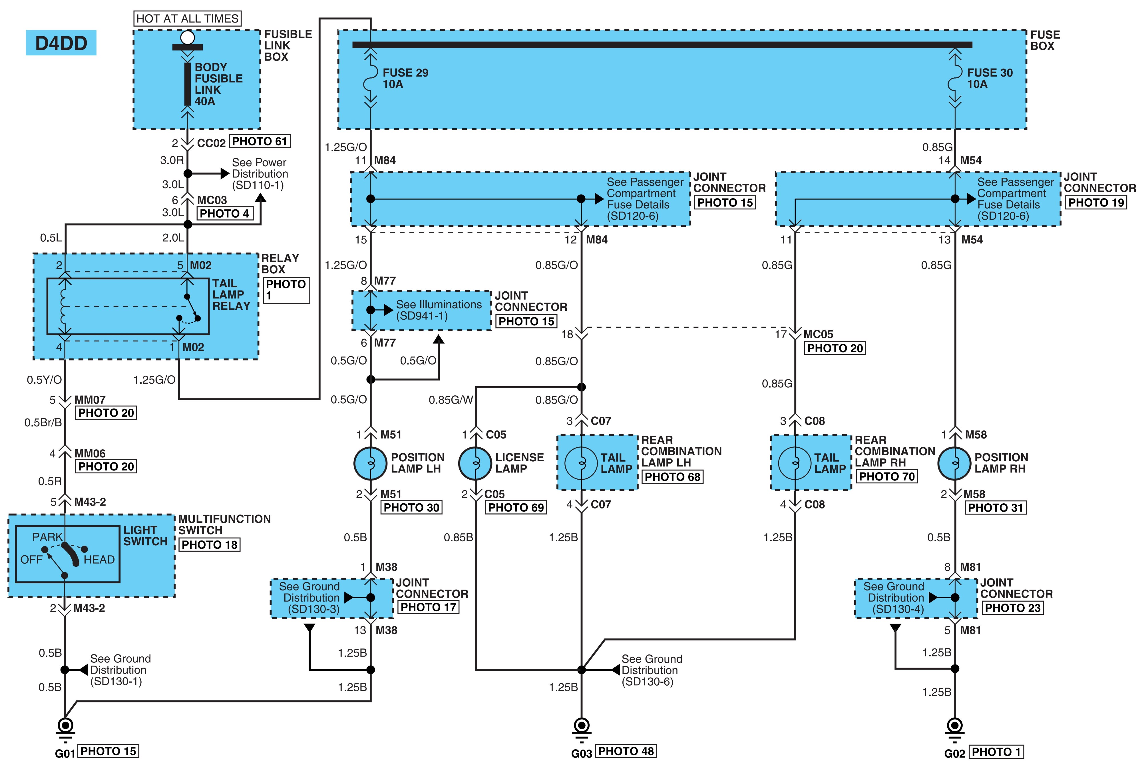
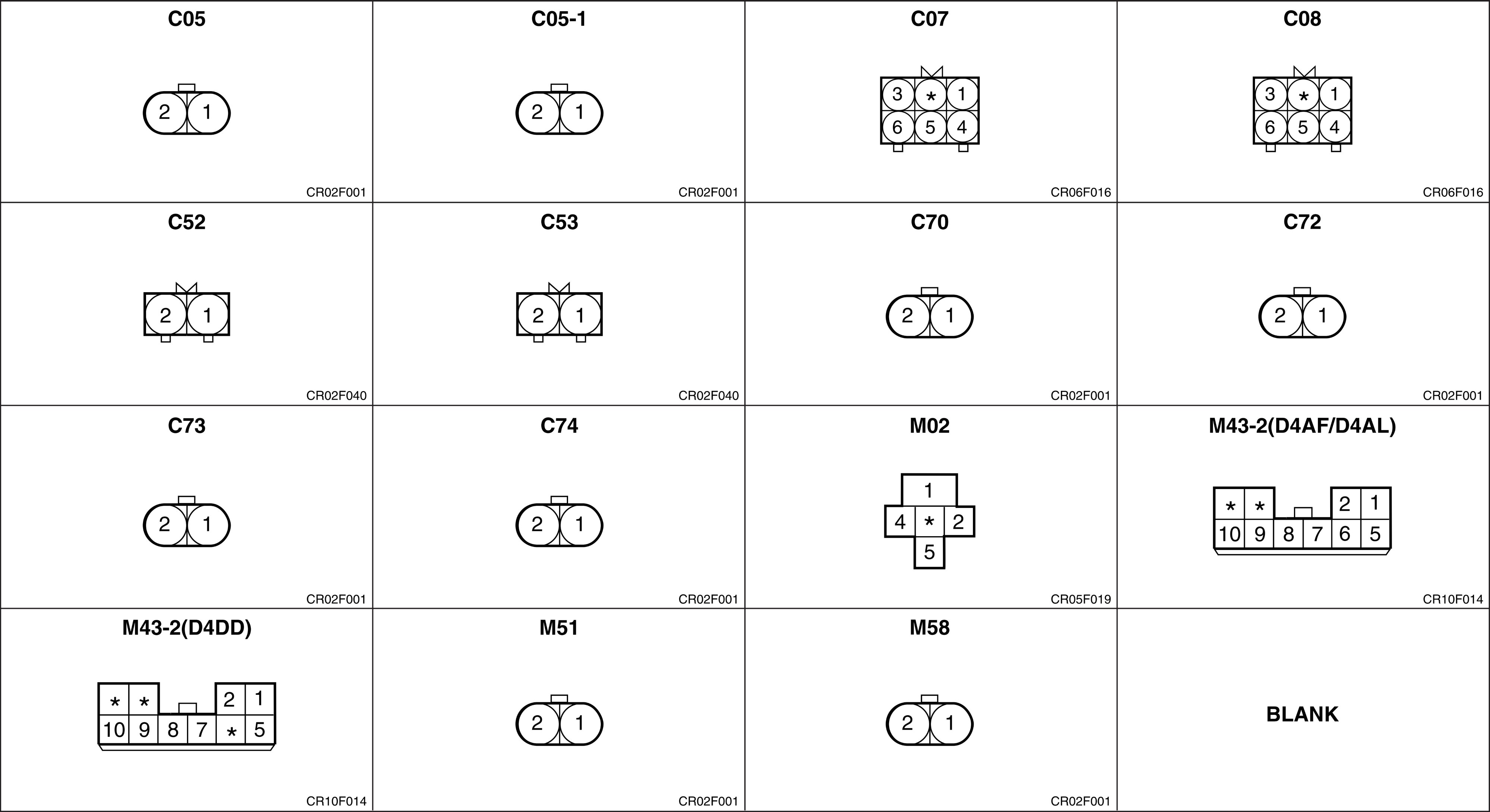
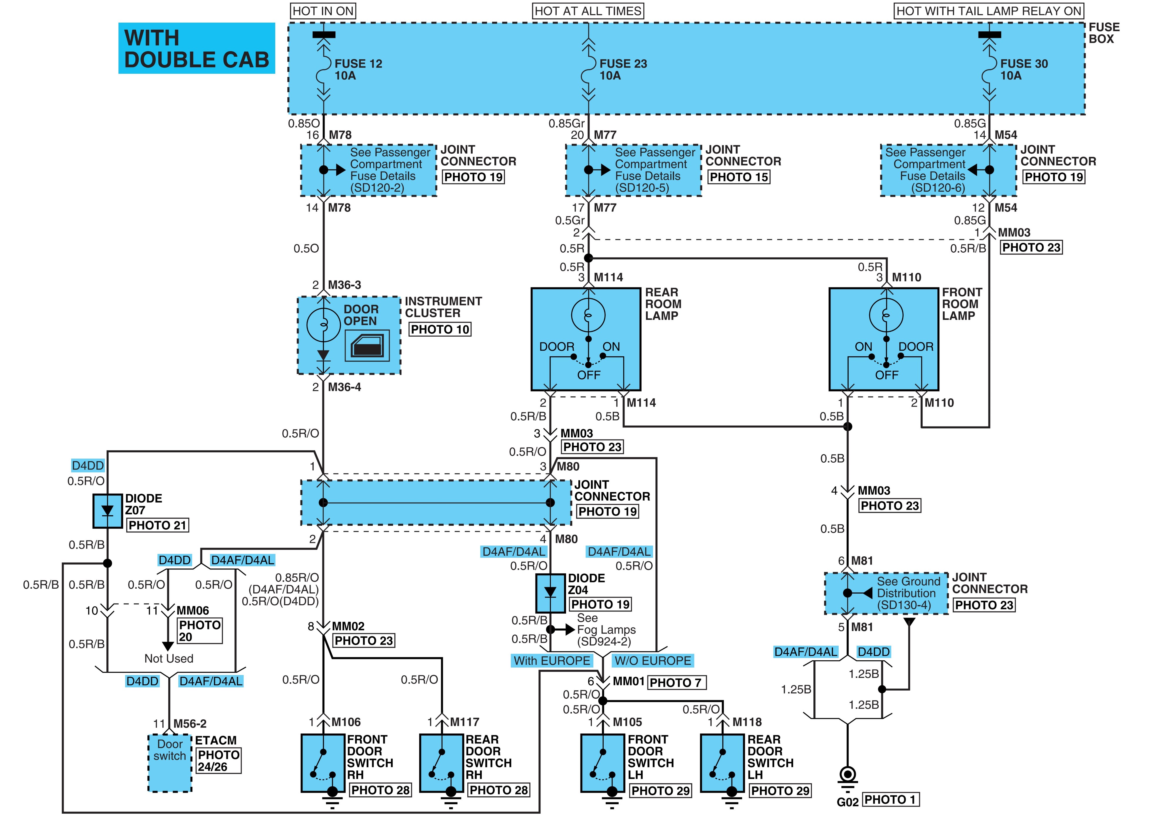
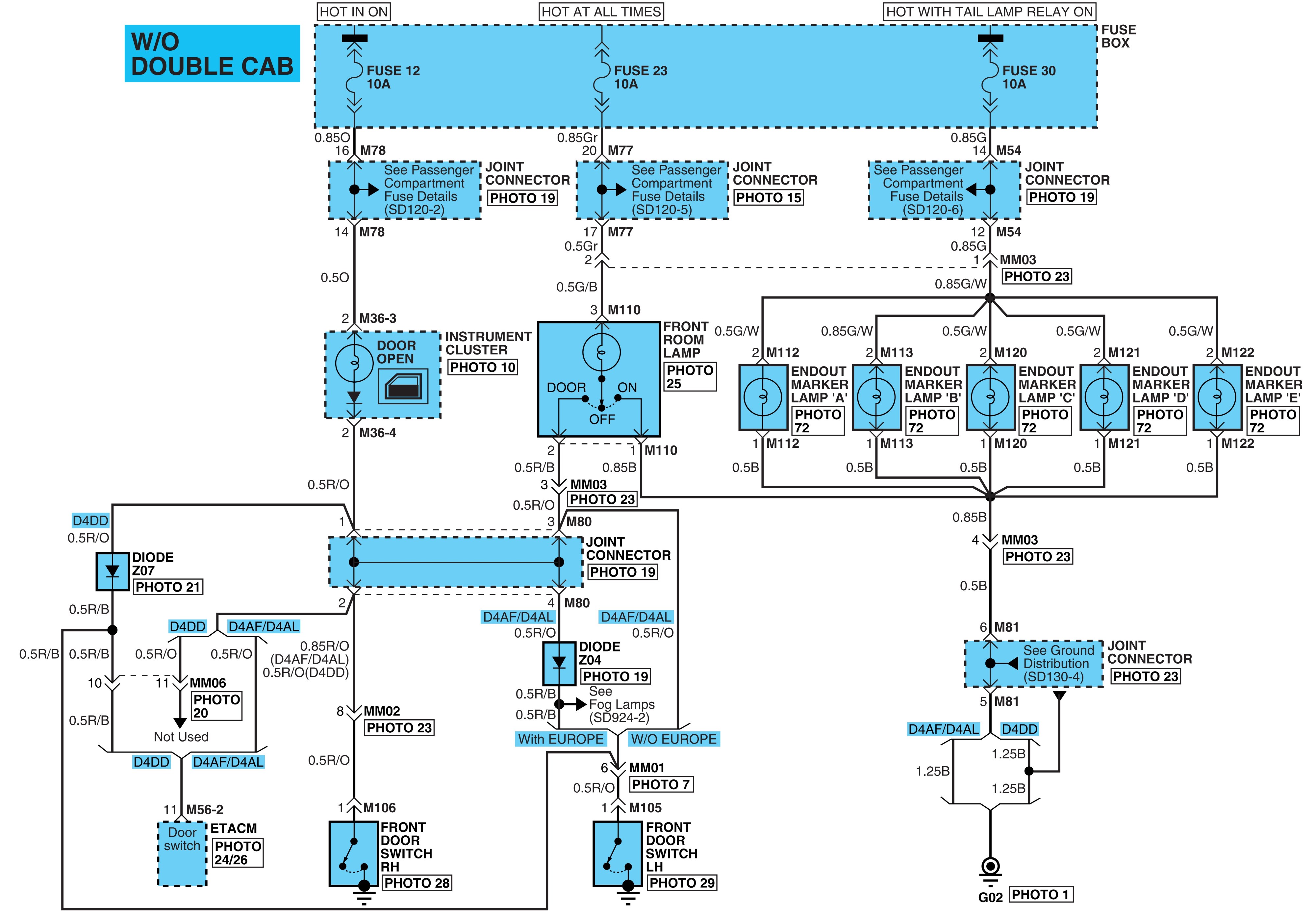
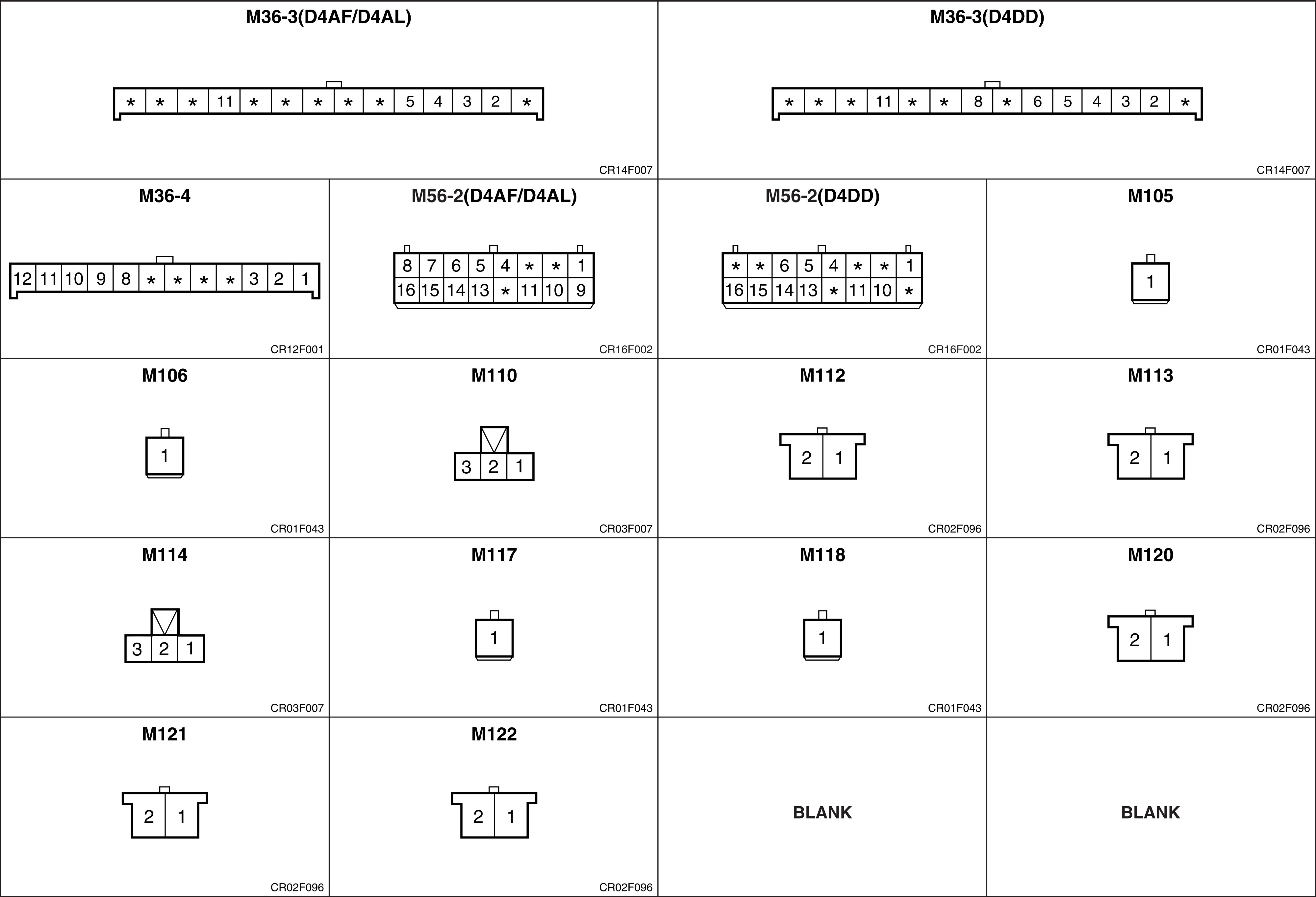
Working lamp & dump warning buzzer.
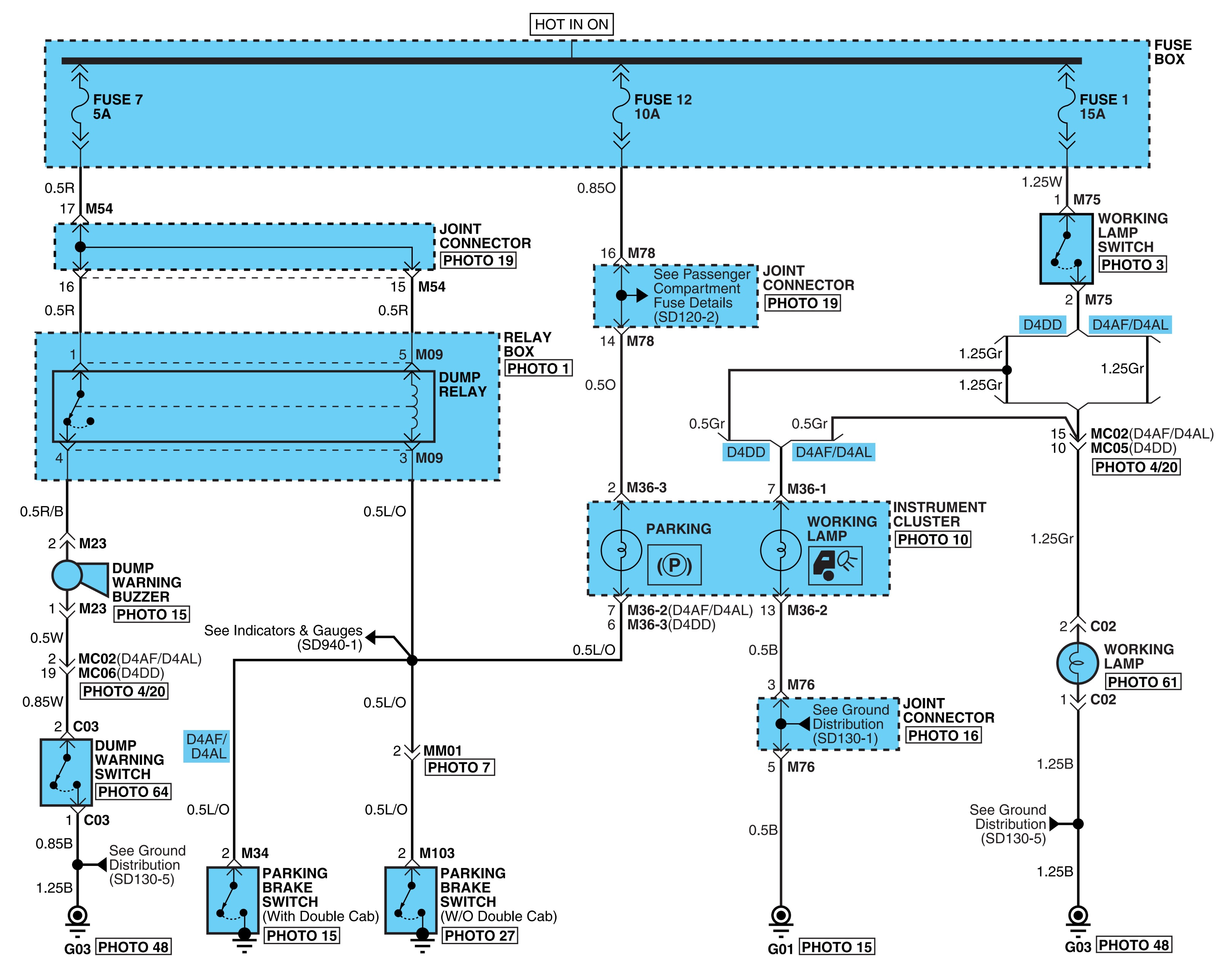
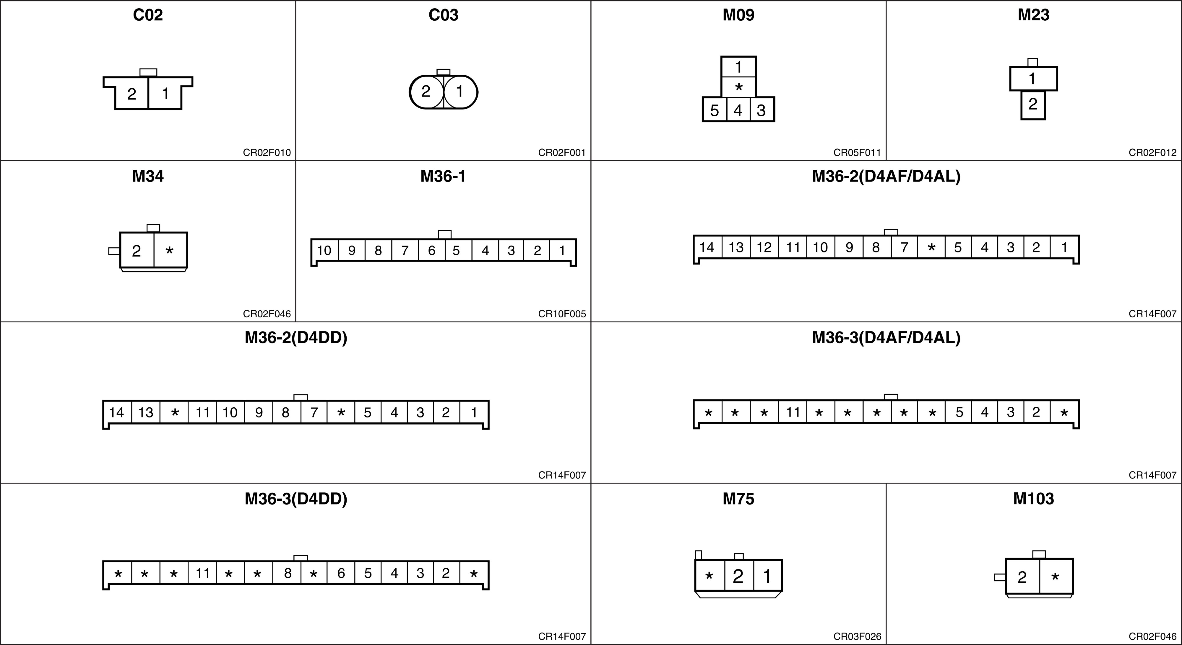
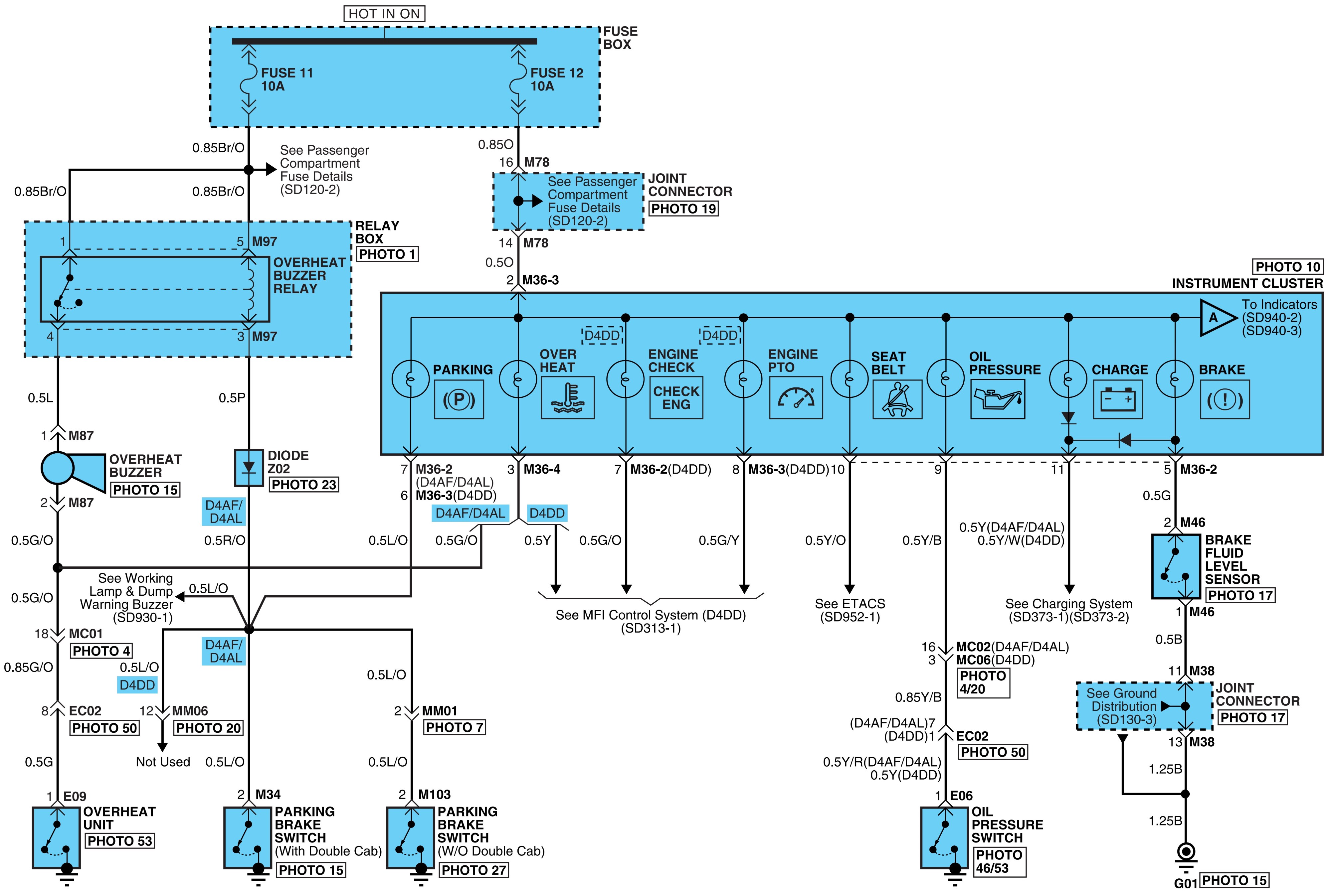
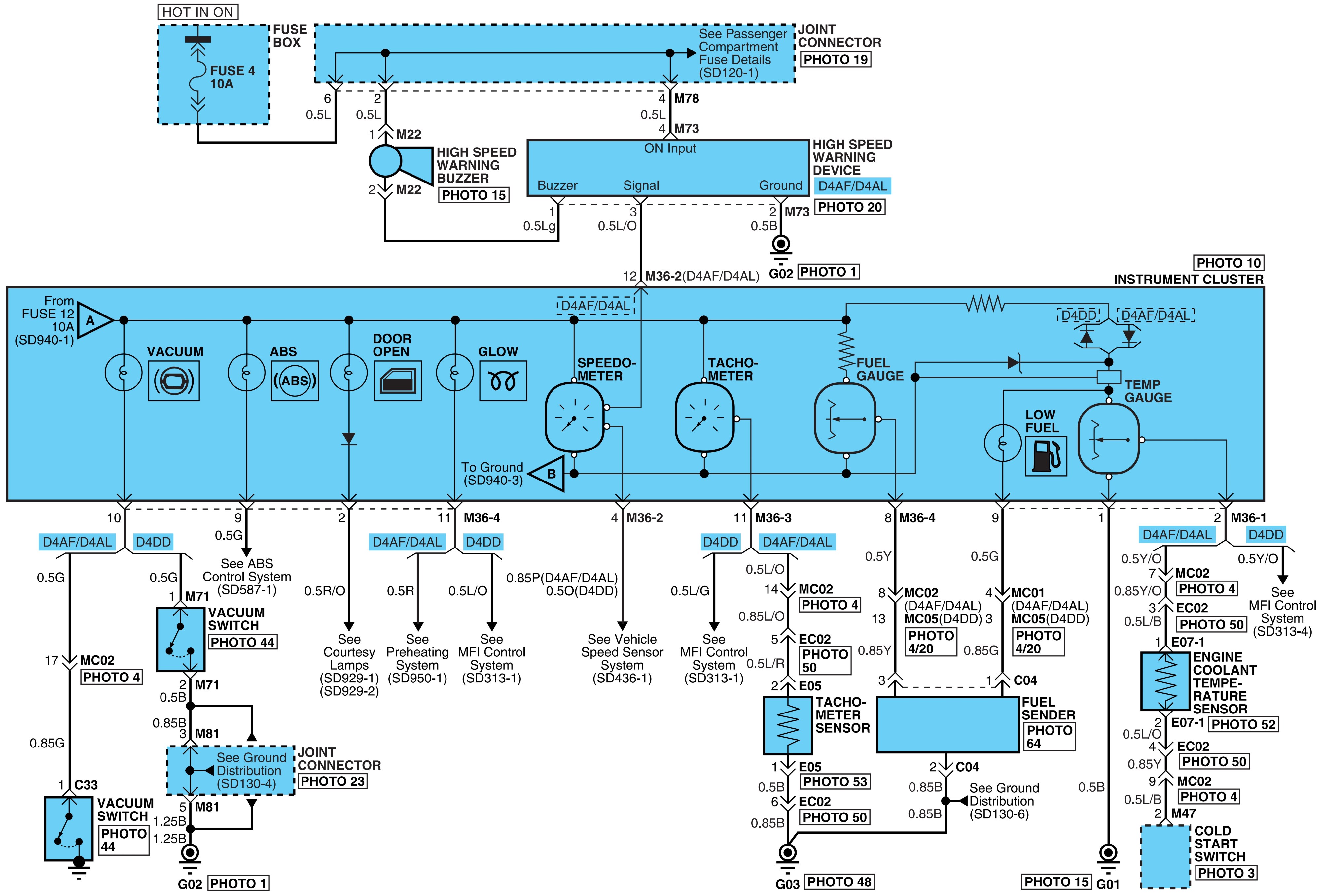
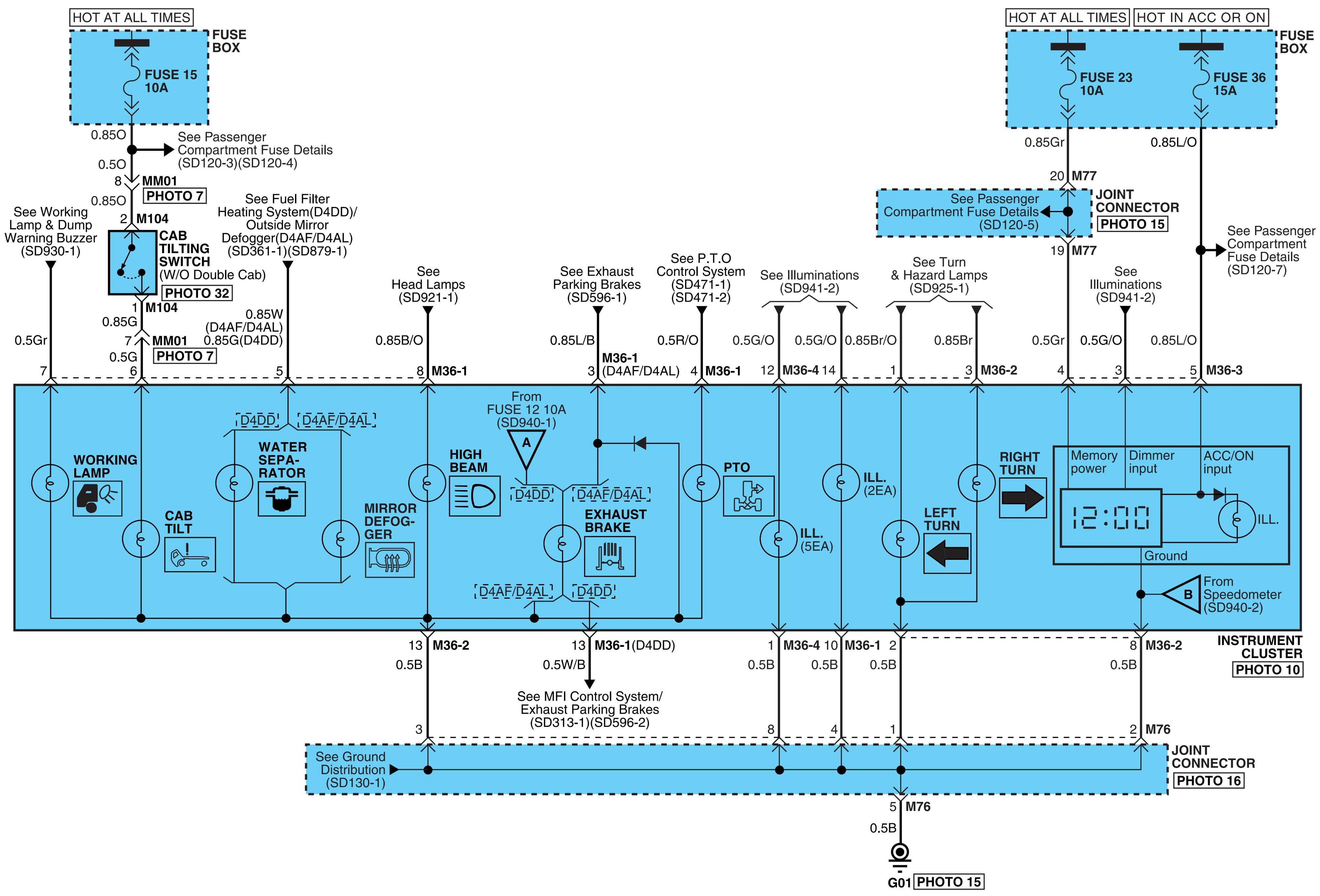
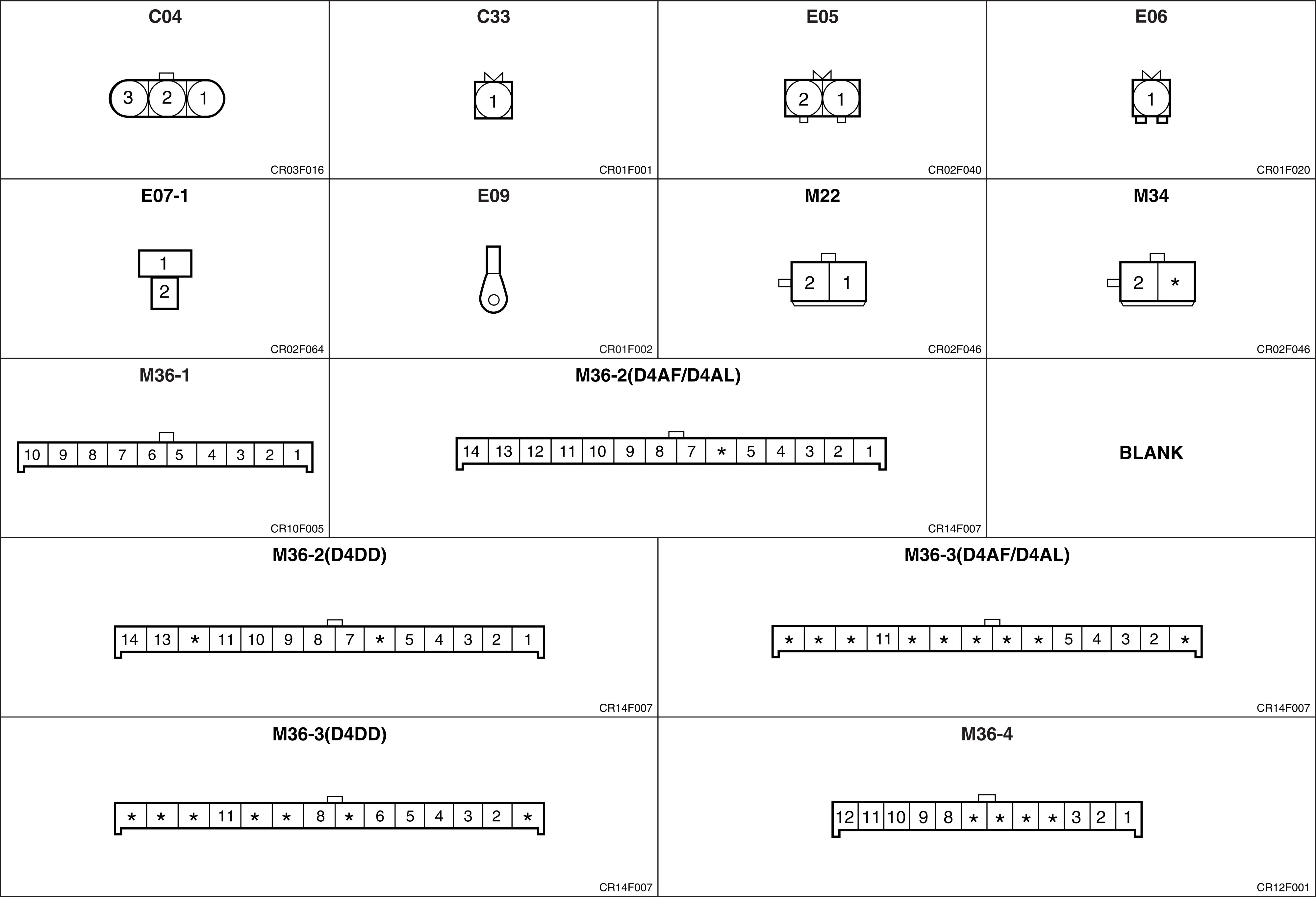
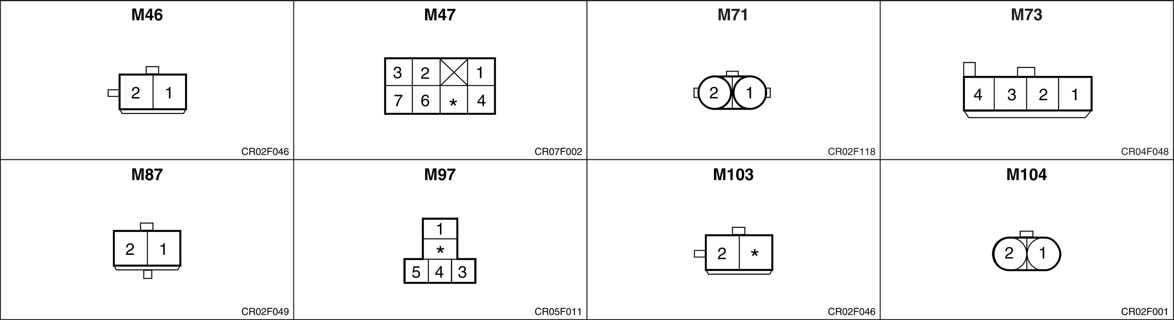
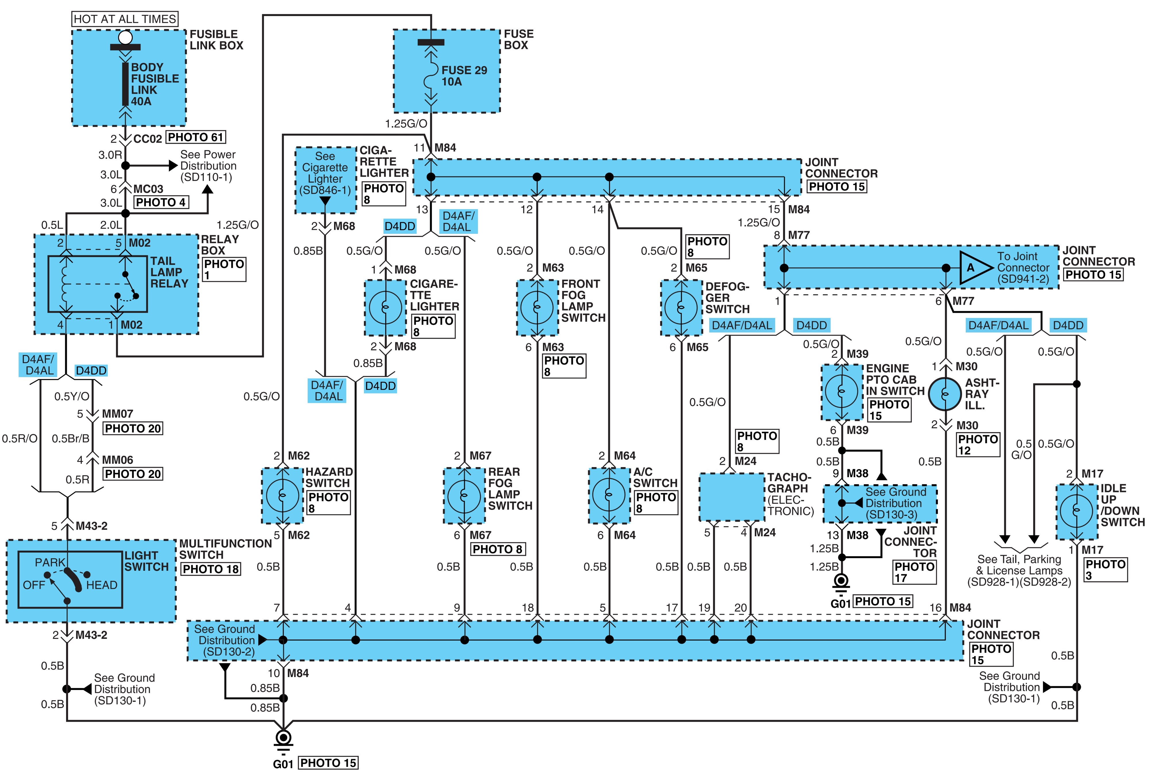
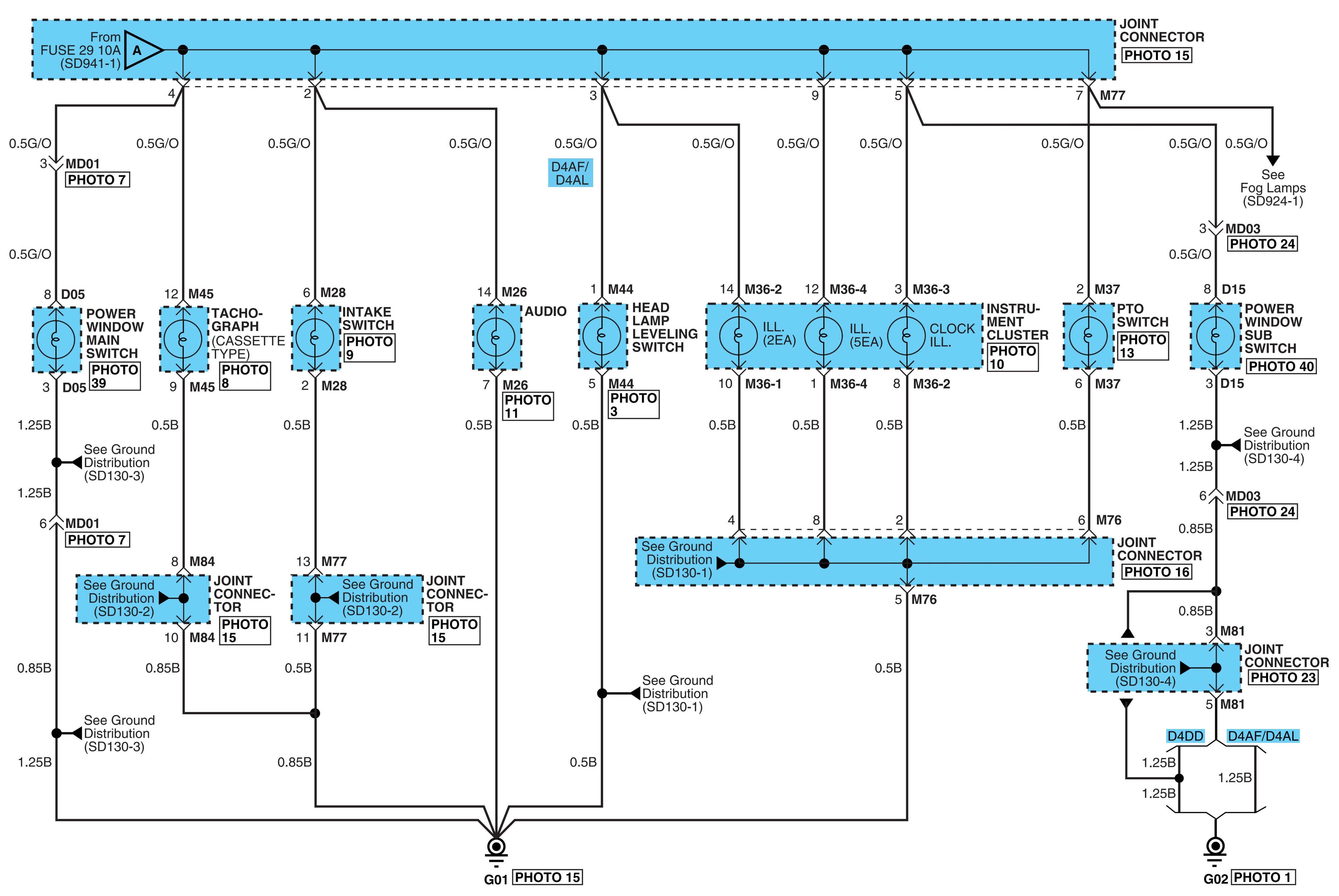
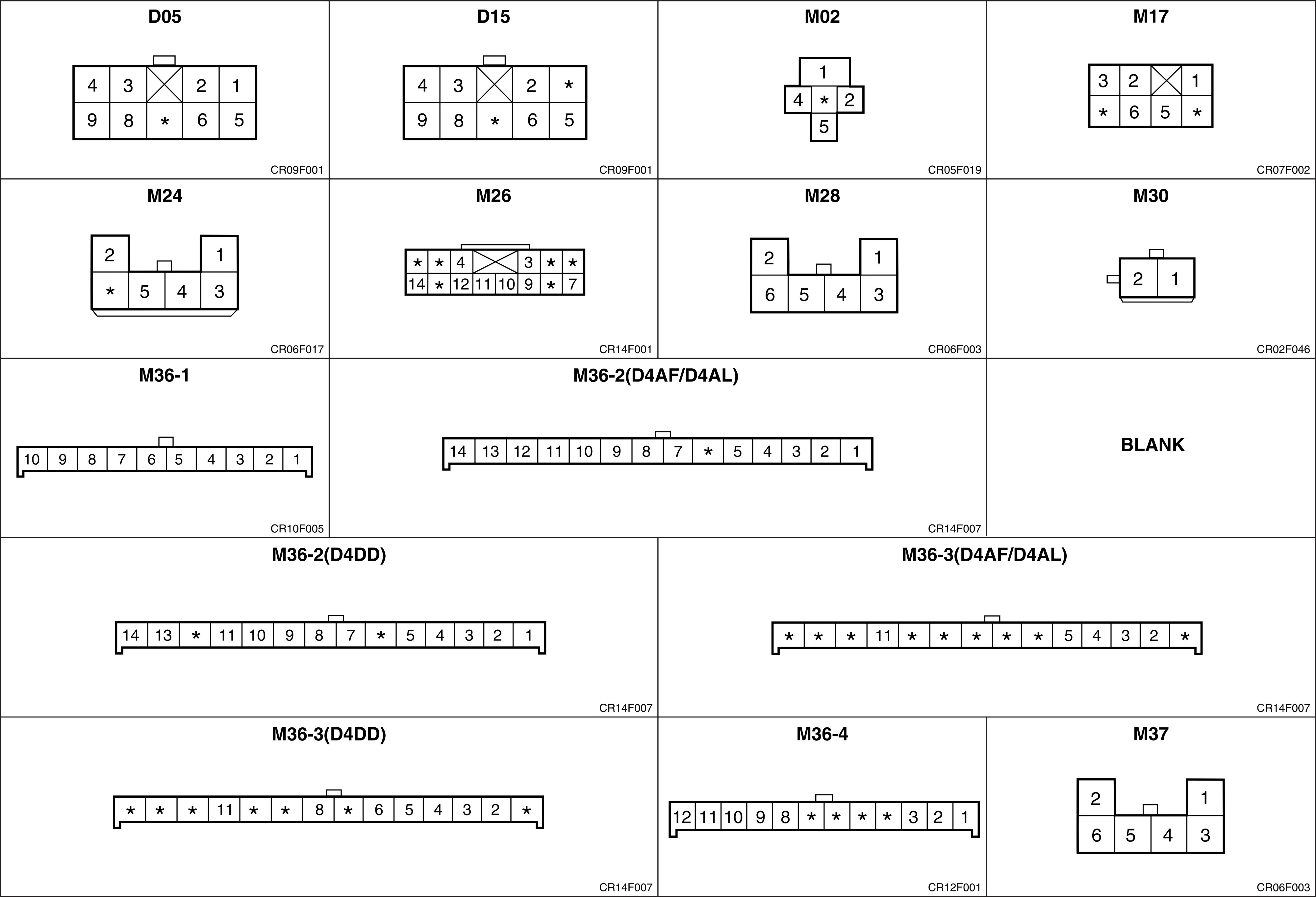
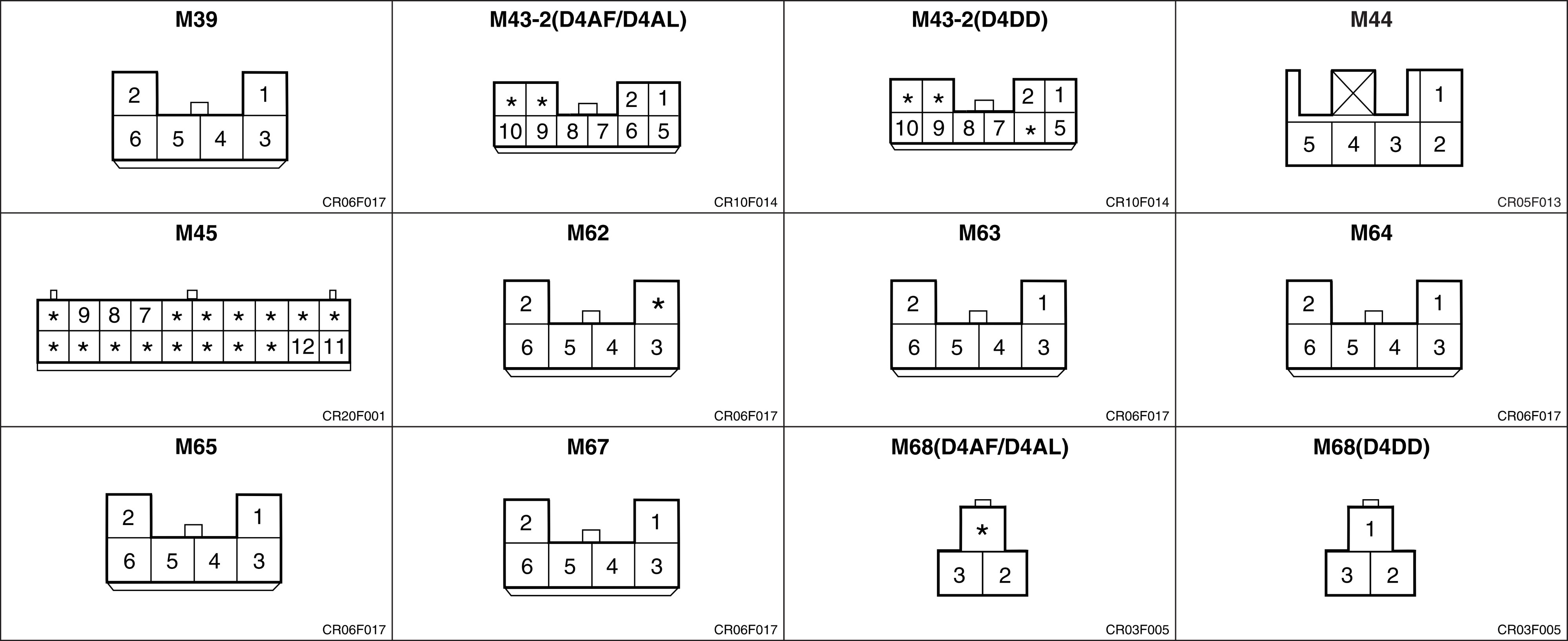
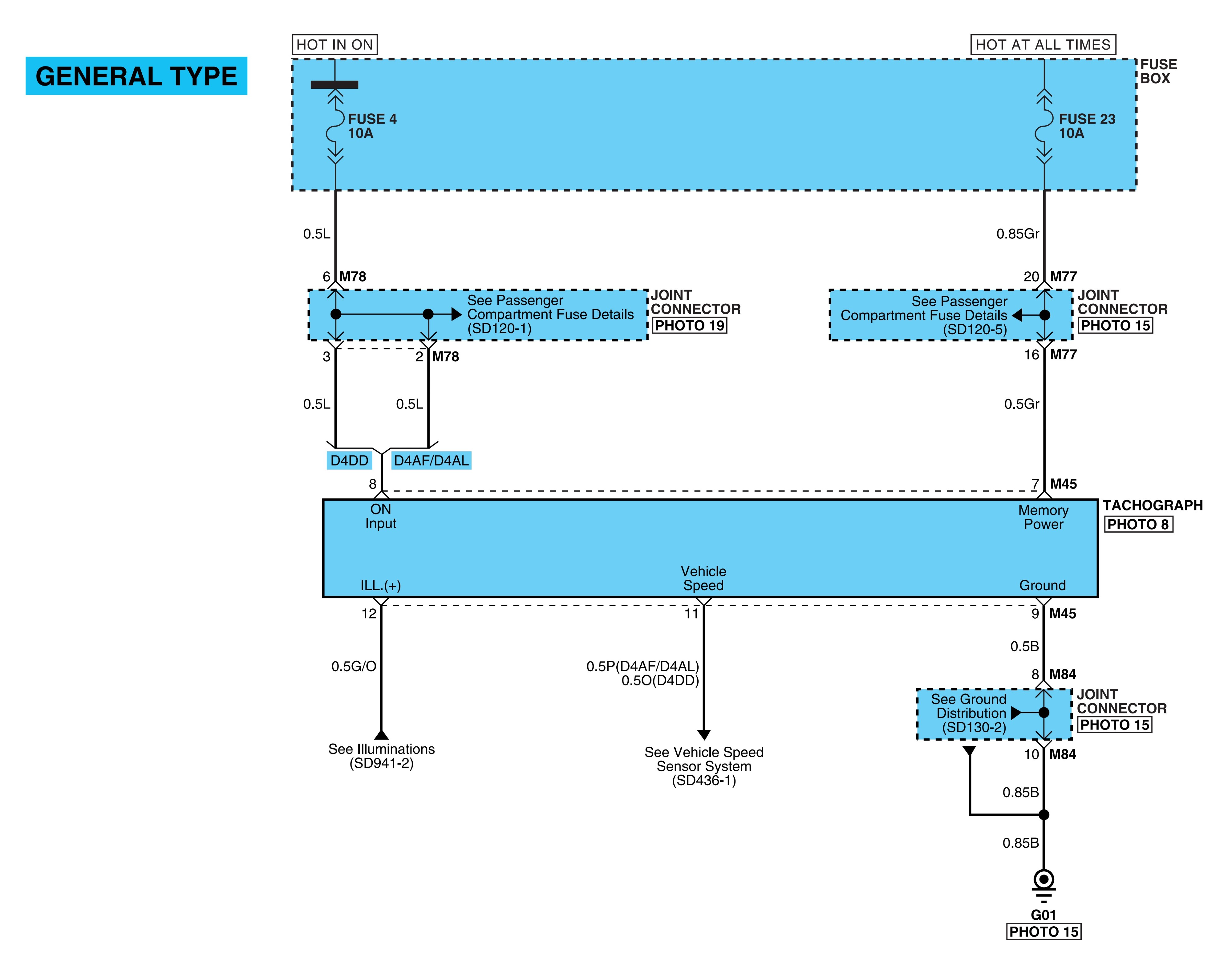
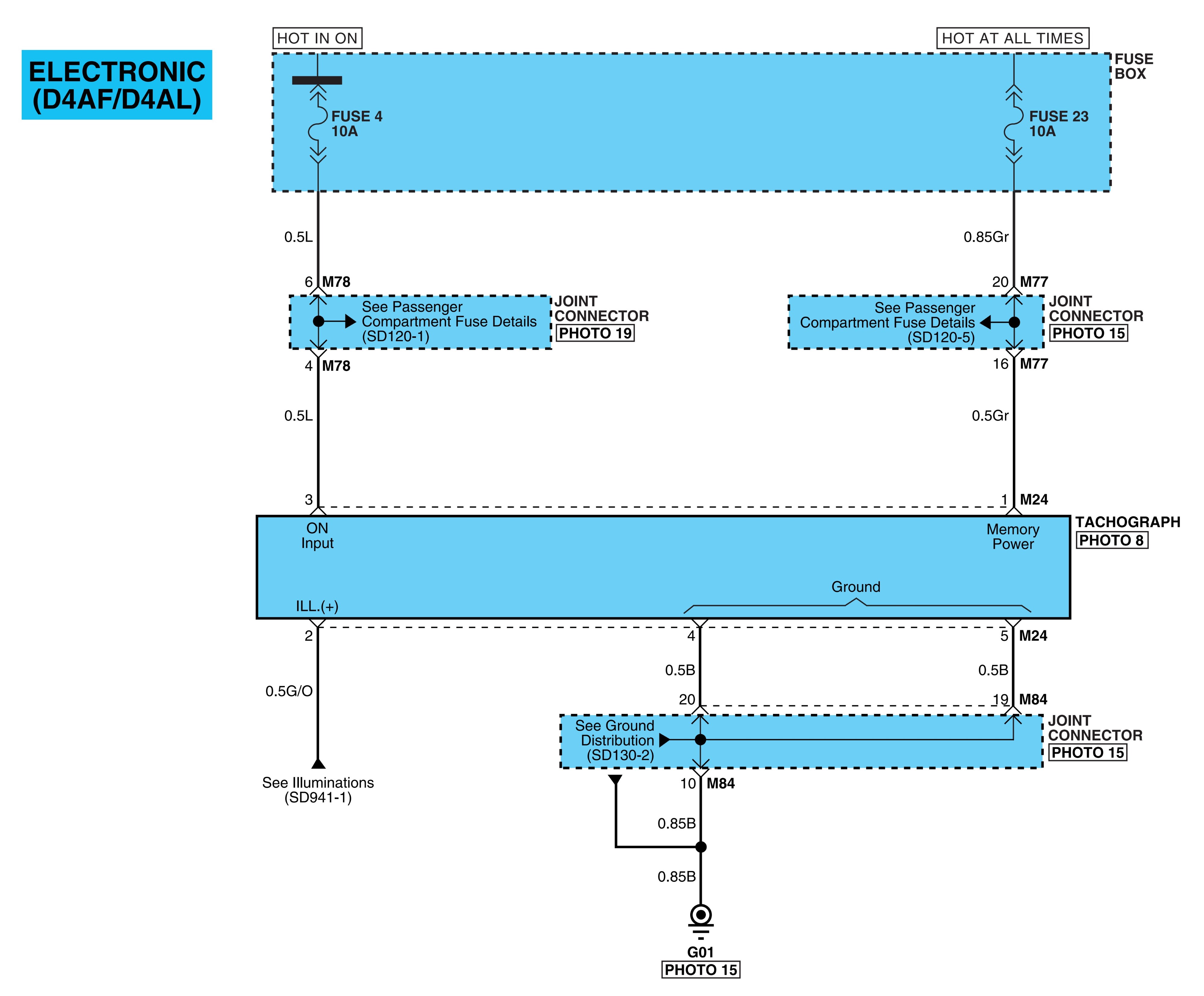

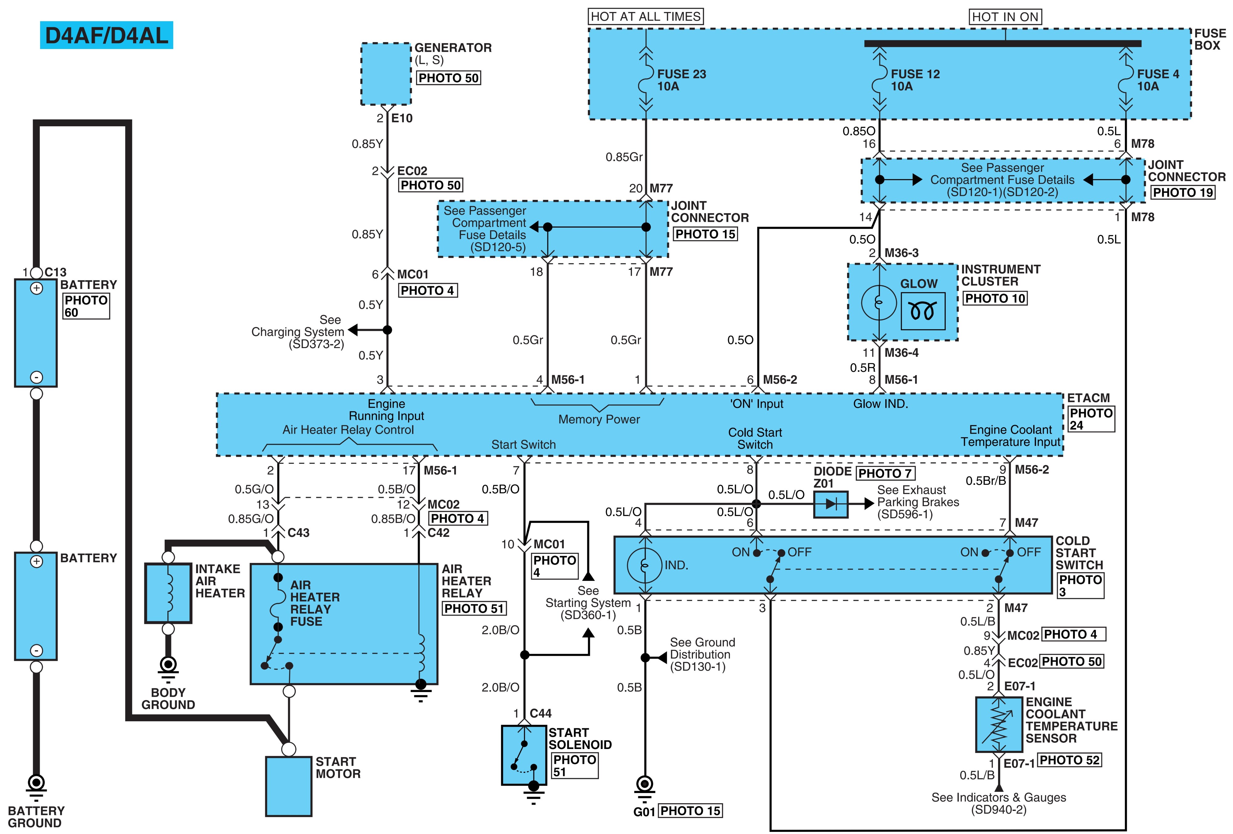
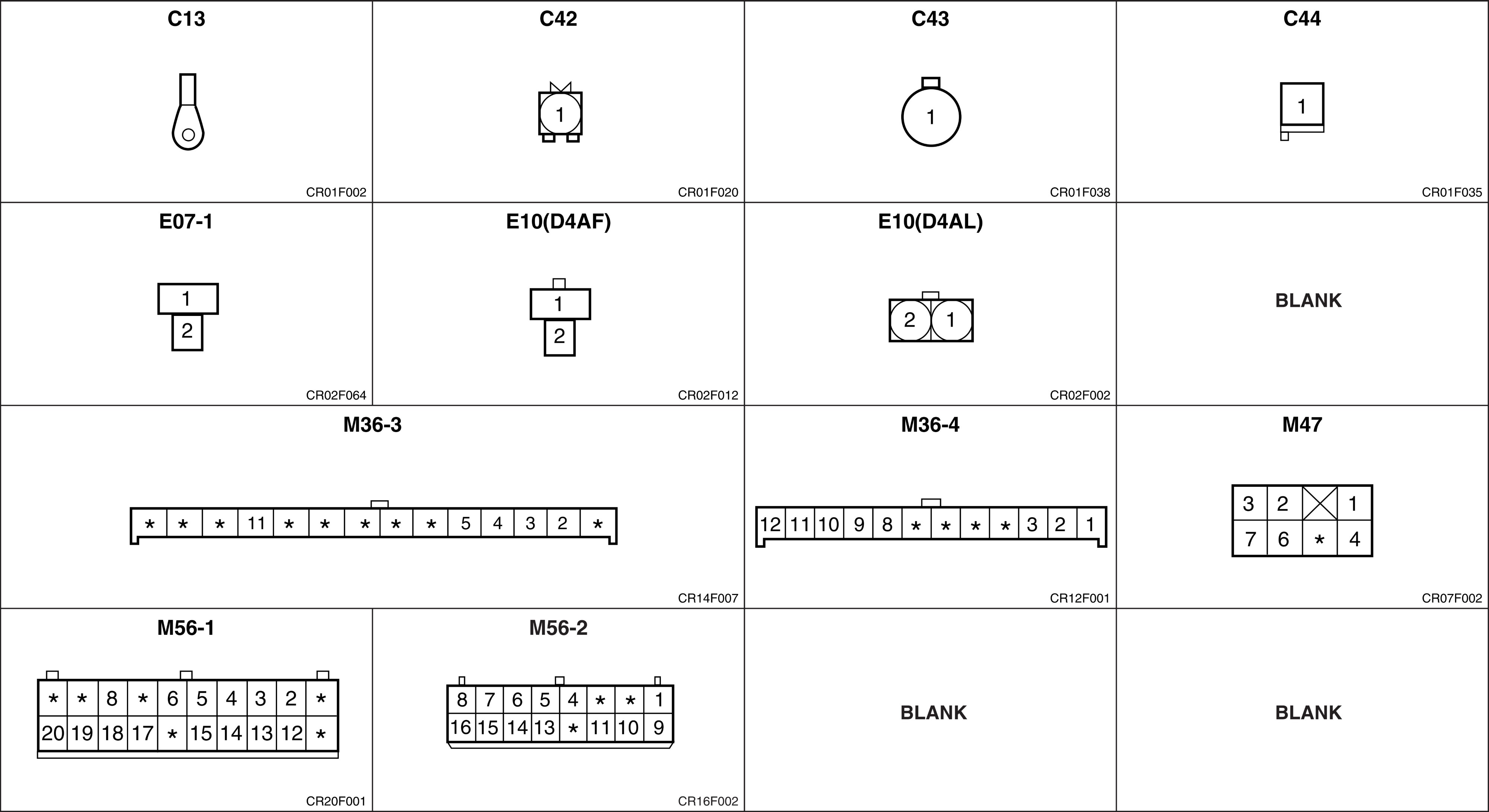
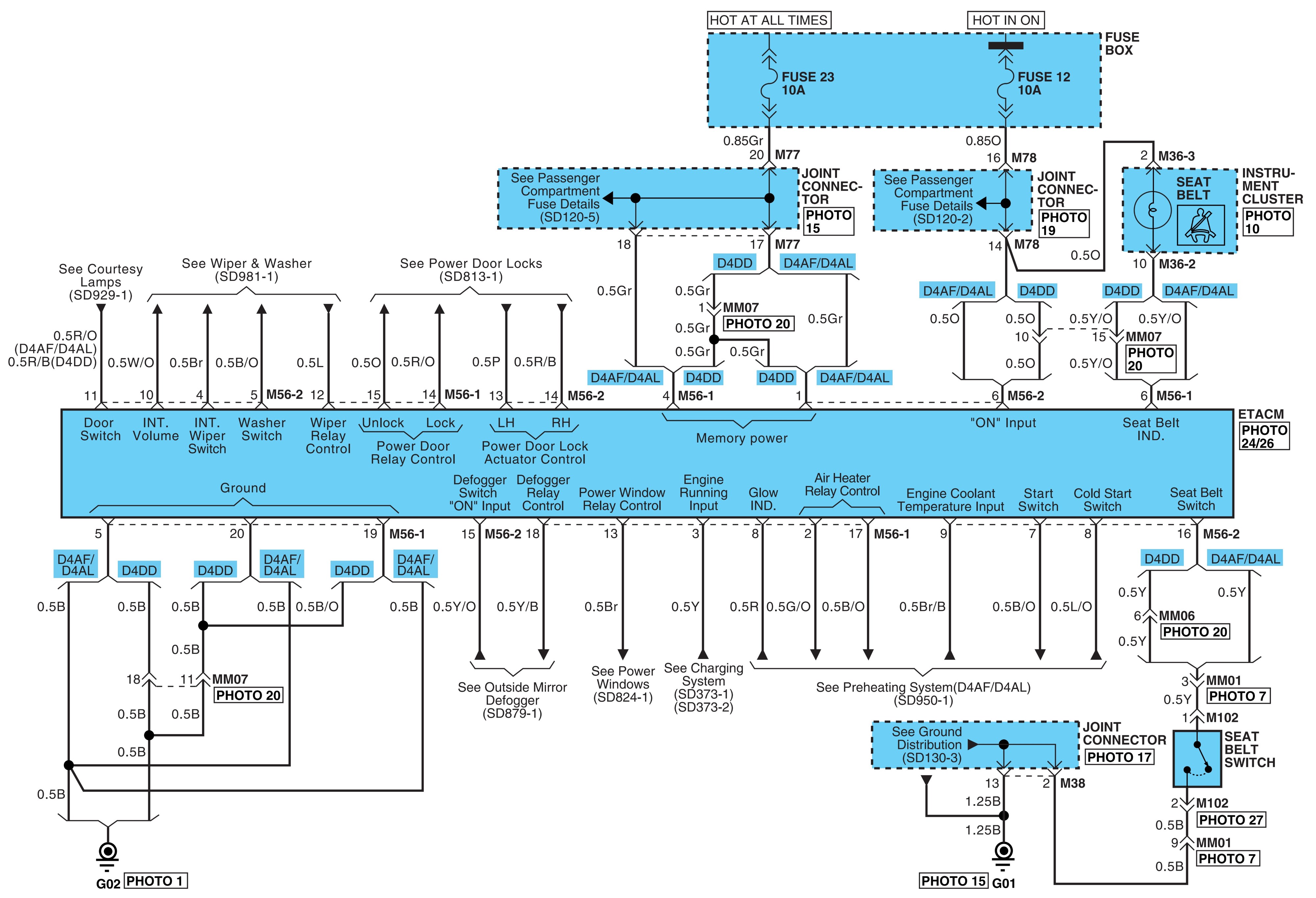
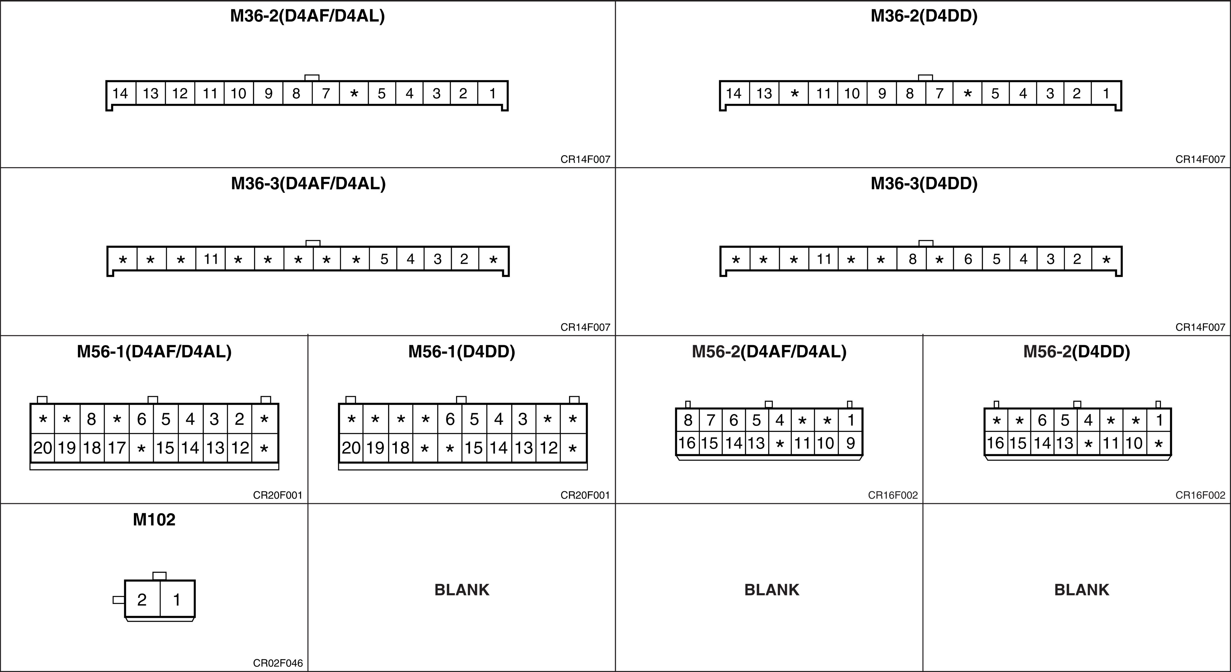
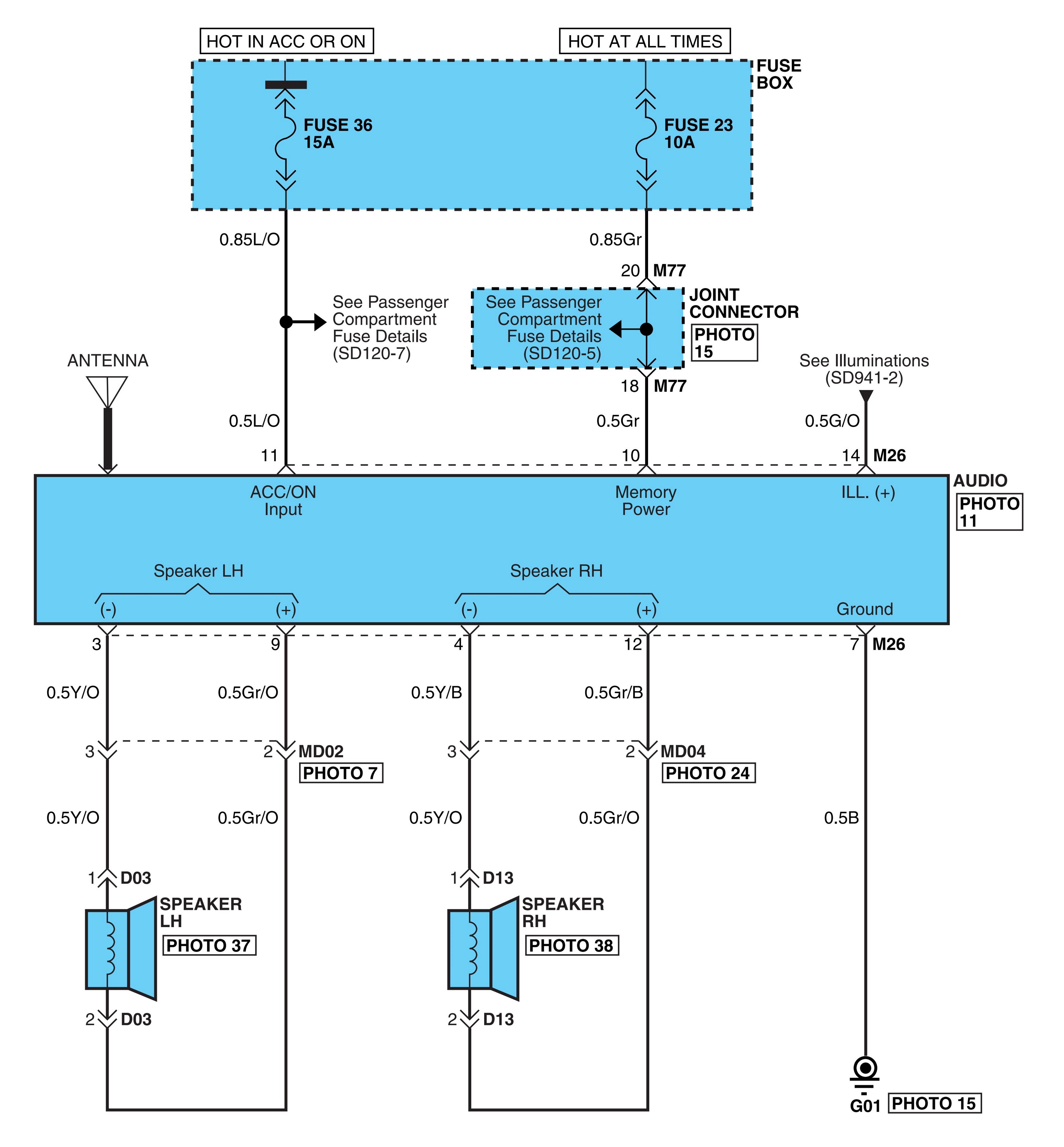

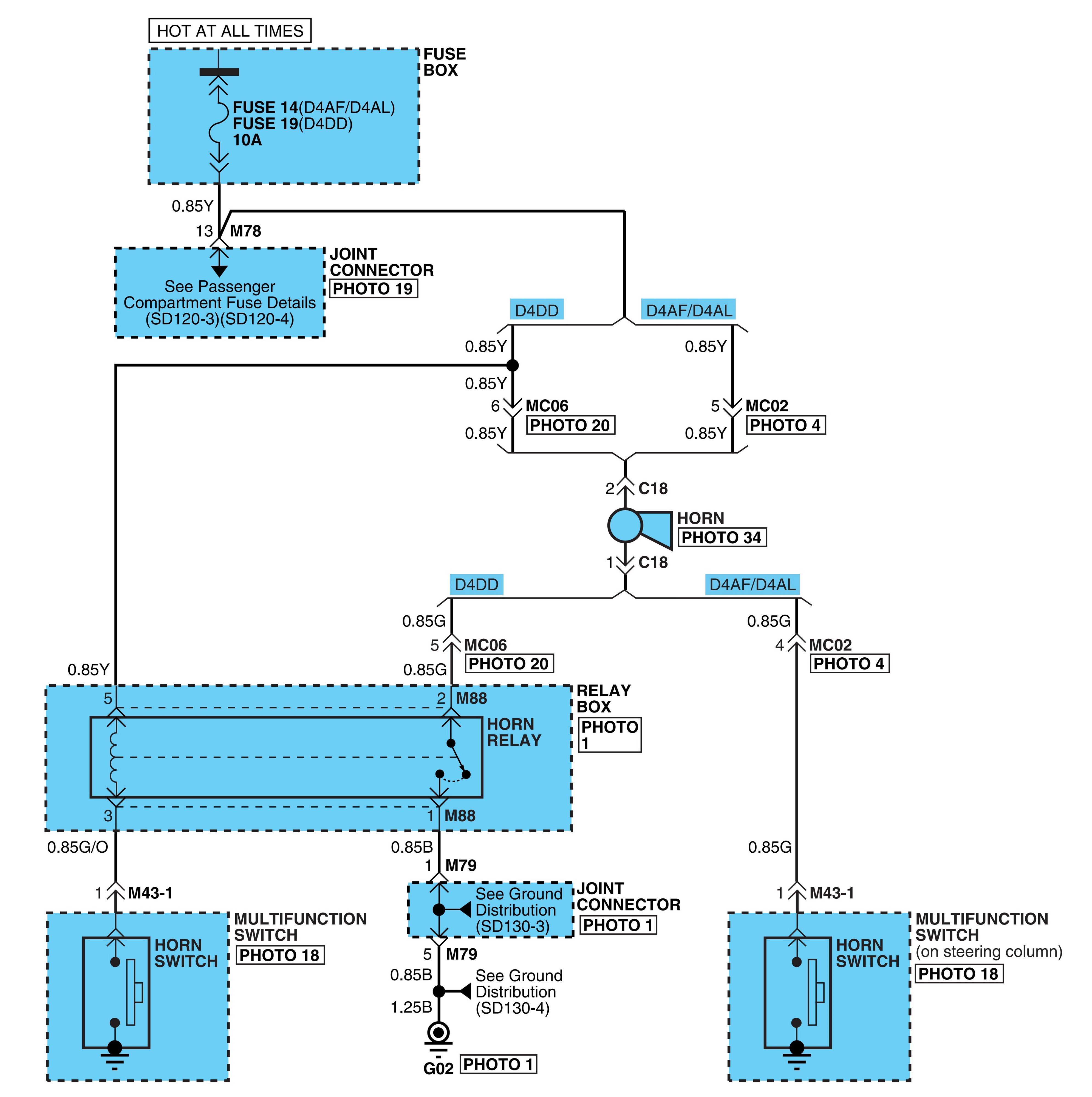

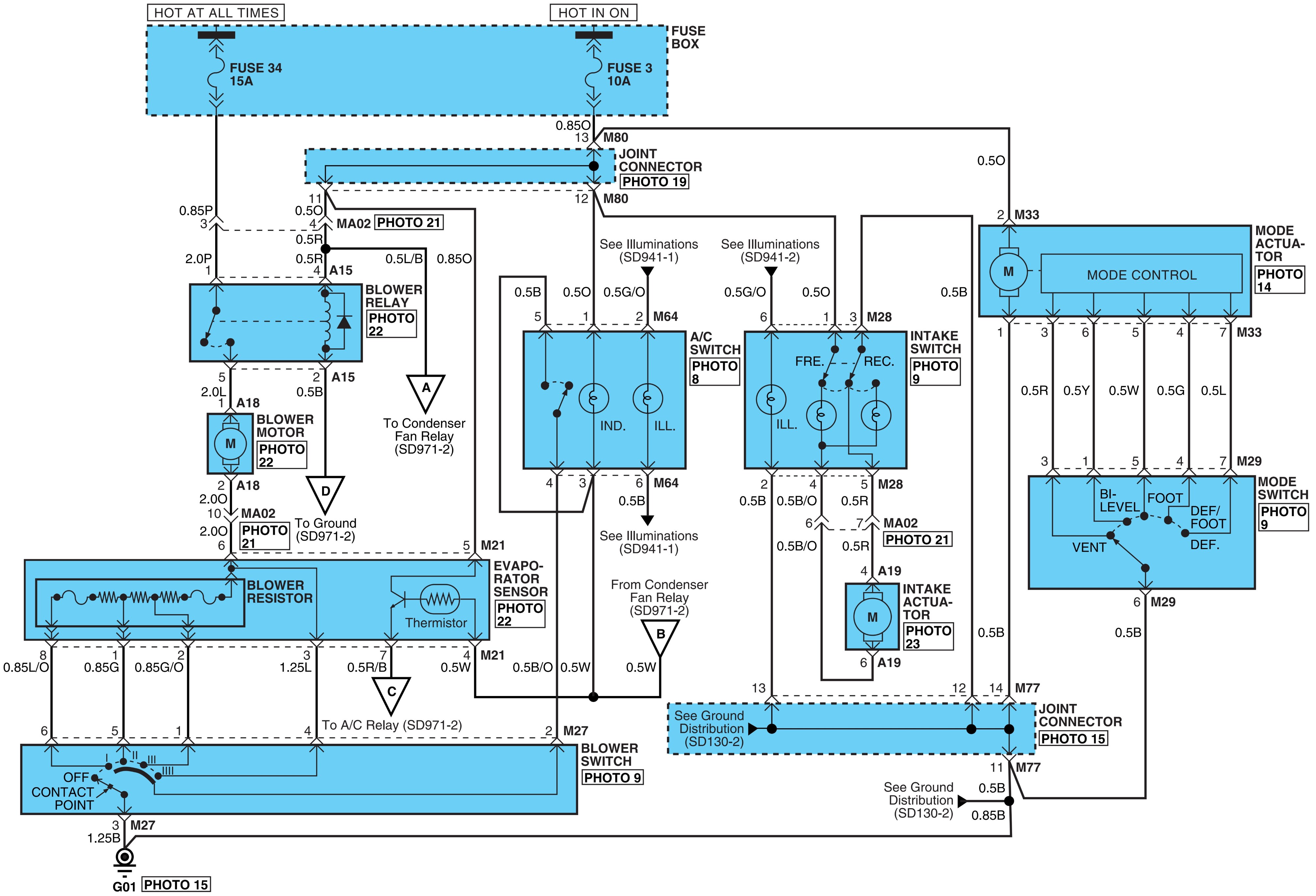
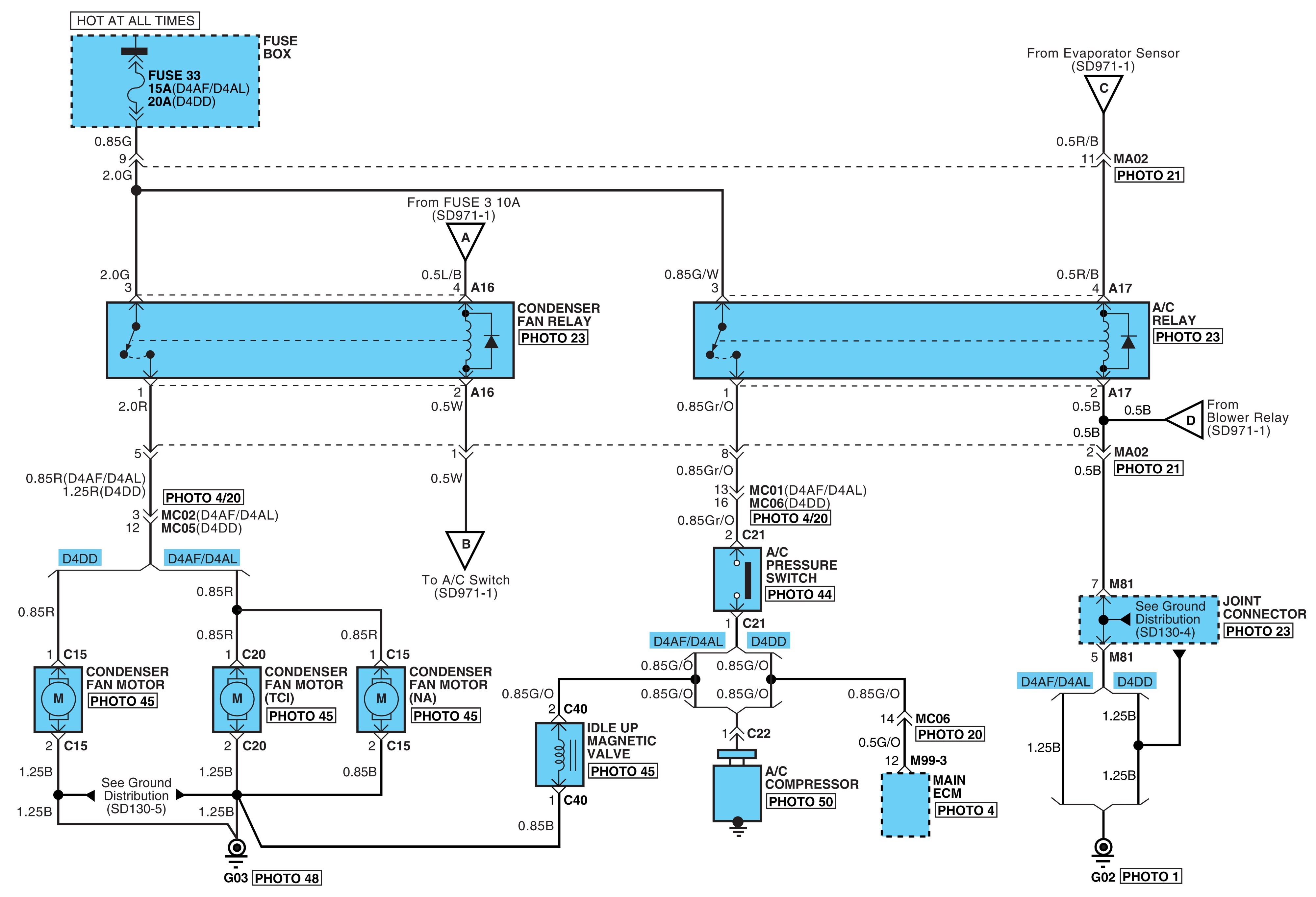
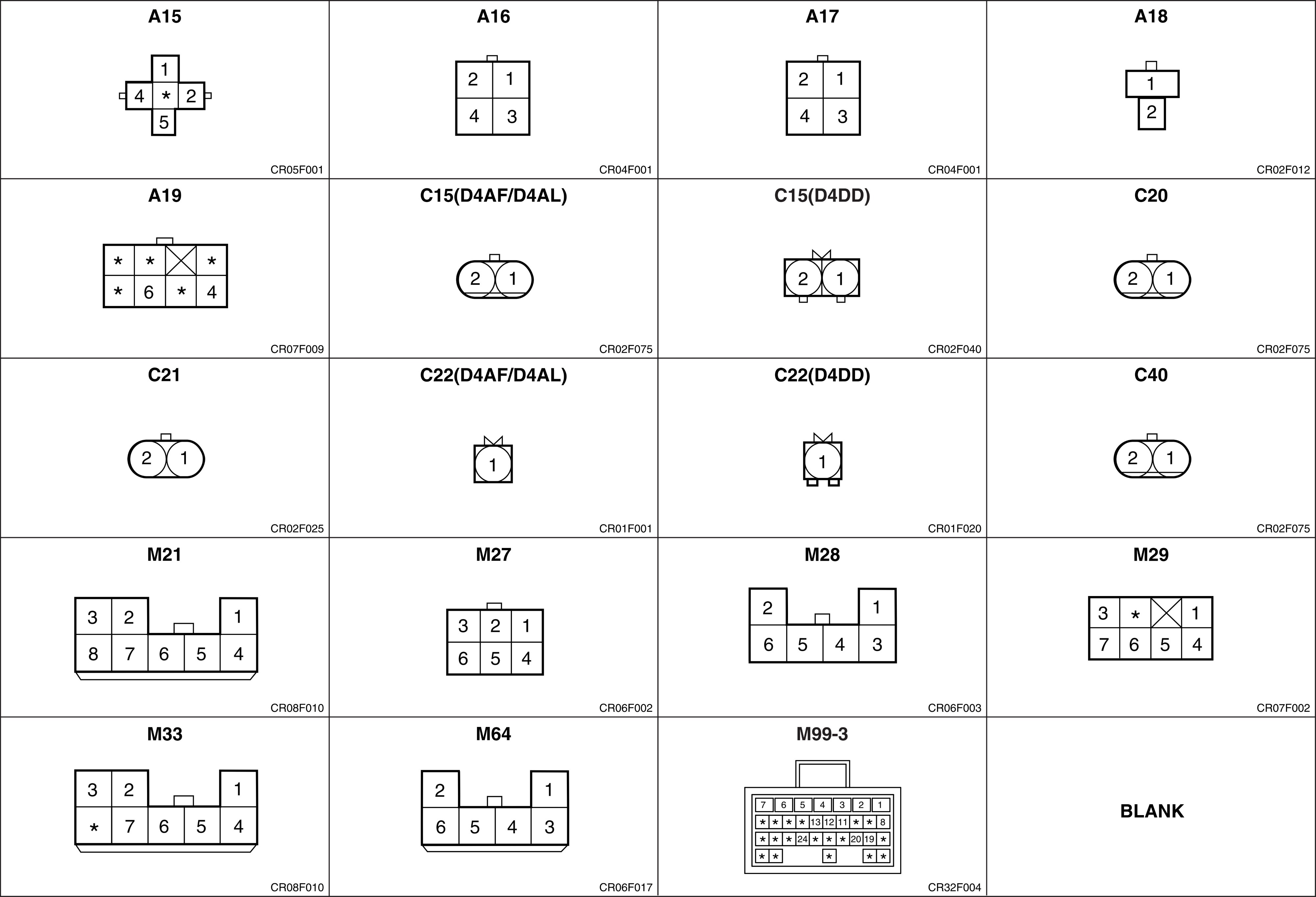
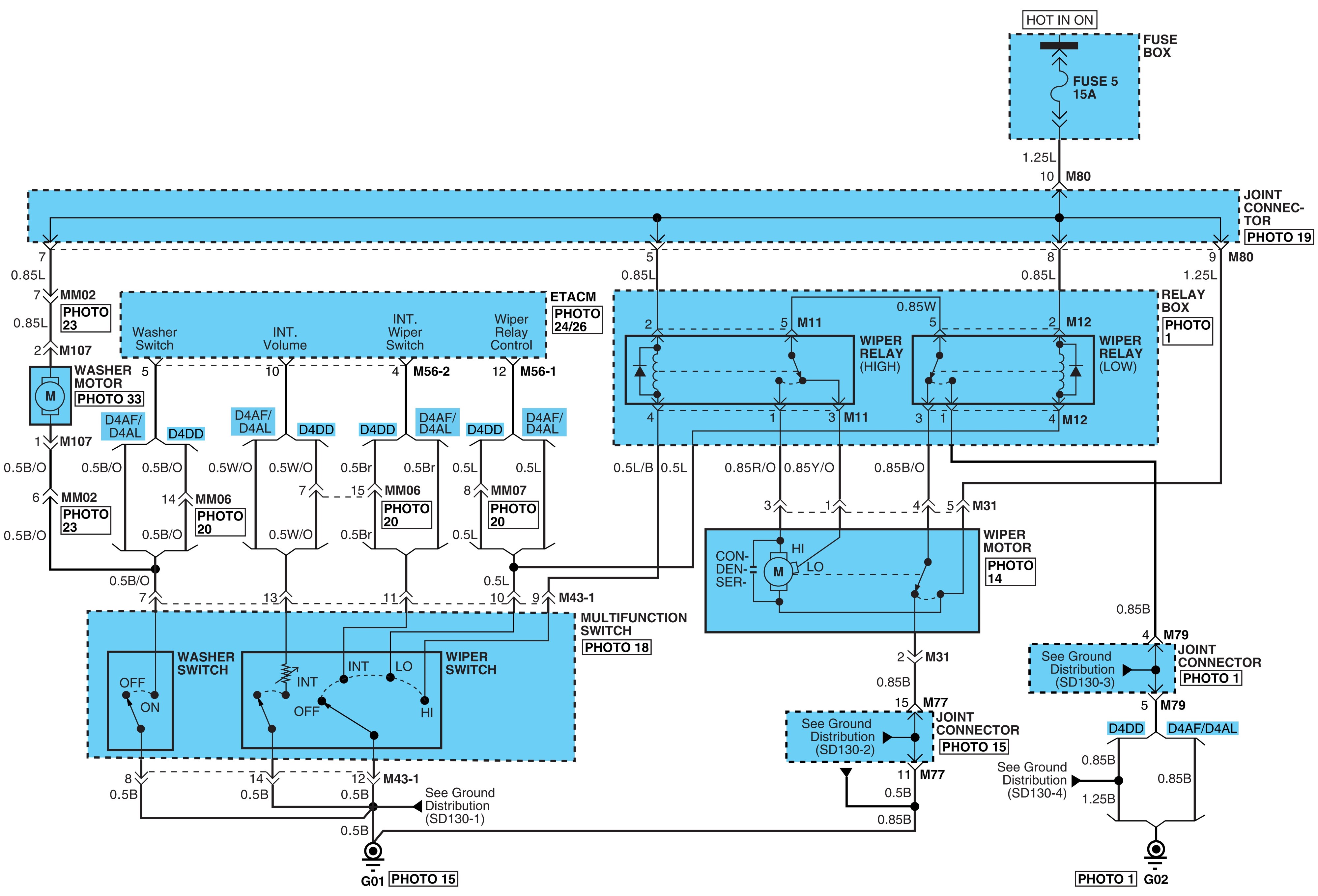
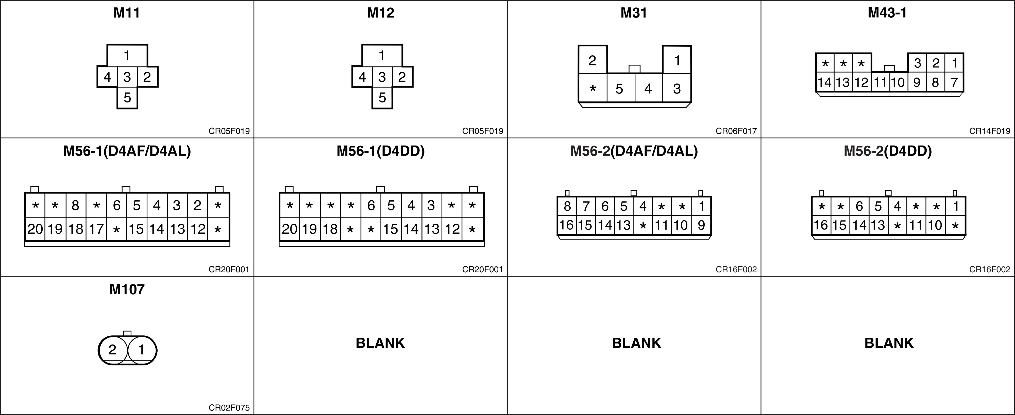
Photo 1-6.
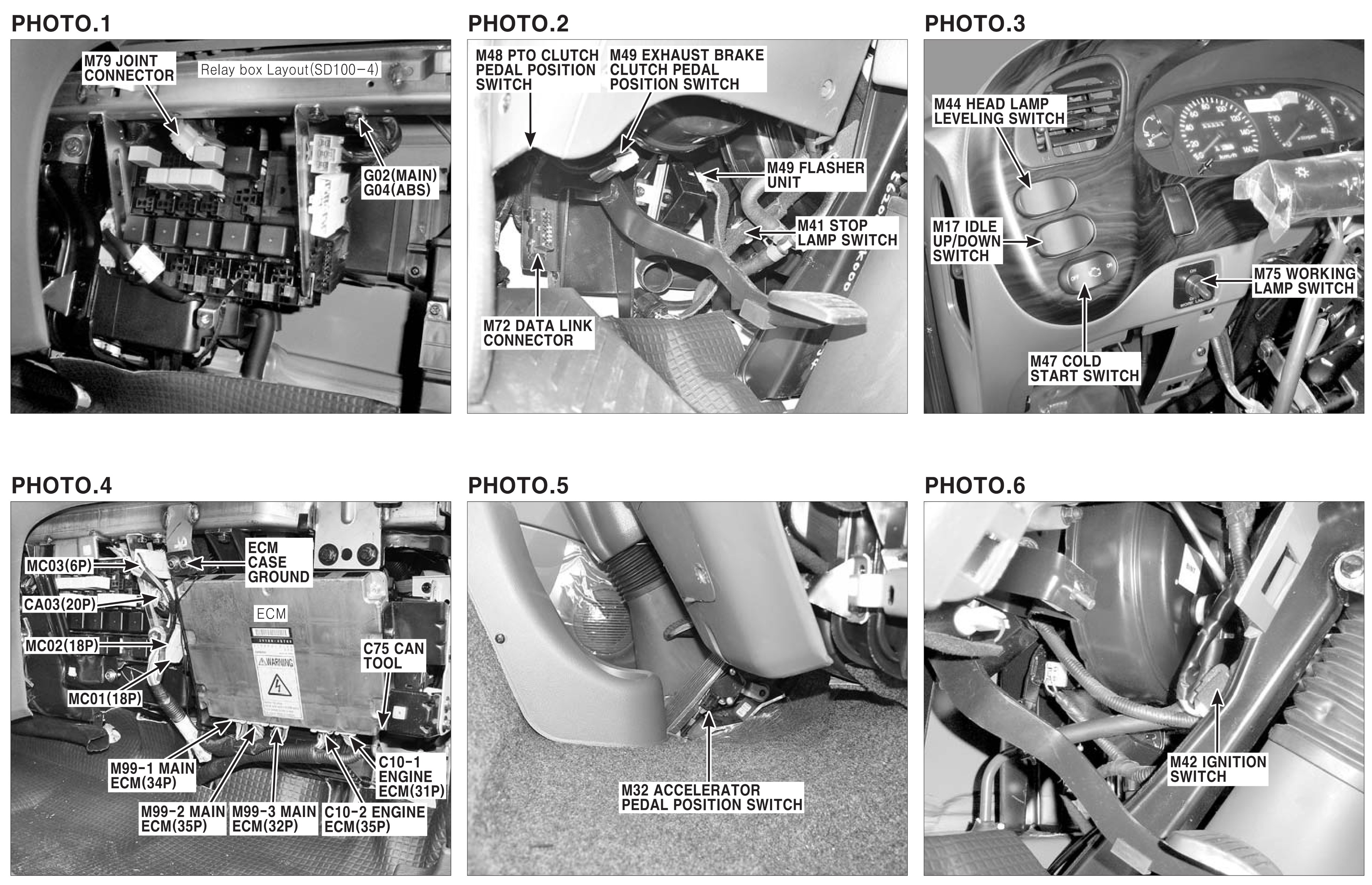
Photo 7-12.
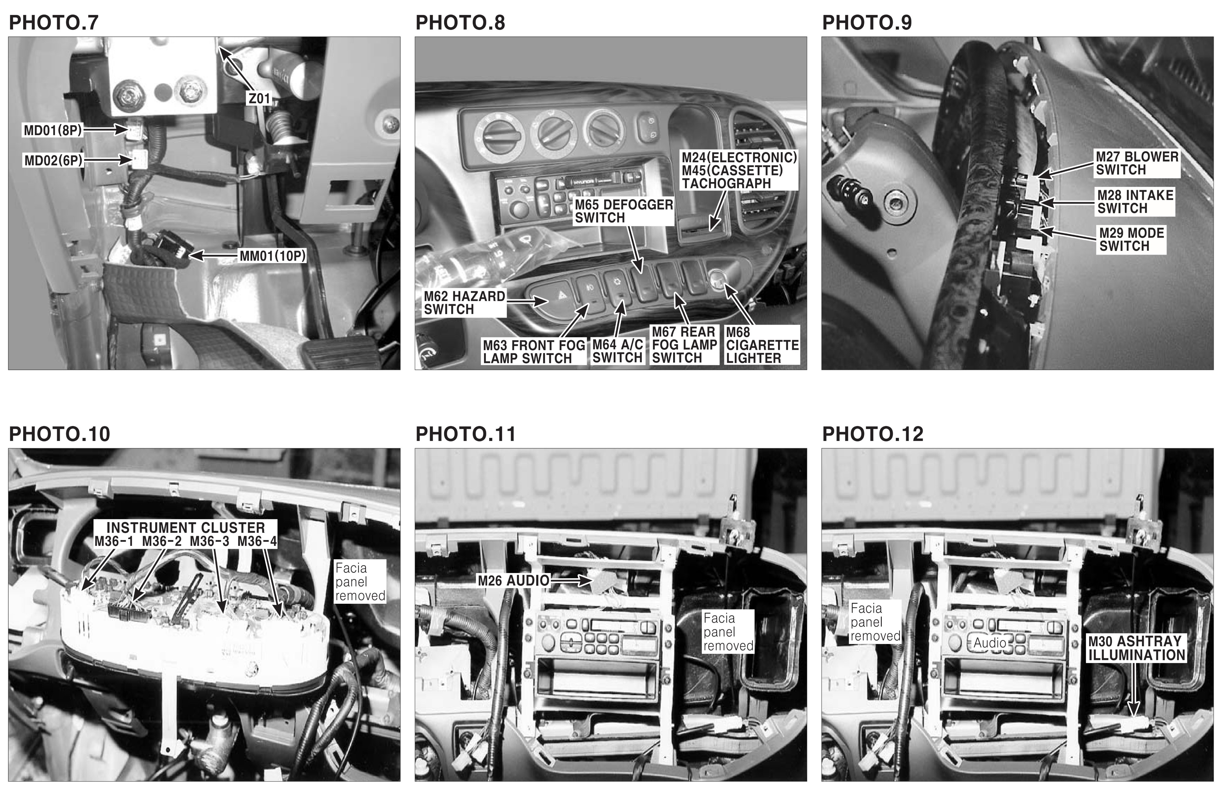
Photo 13-18.
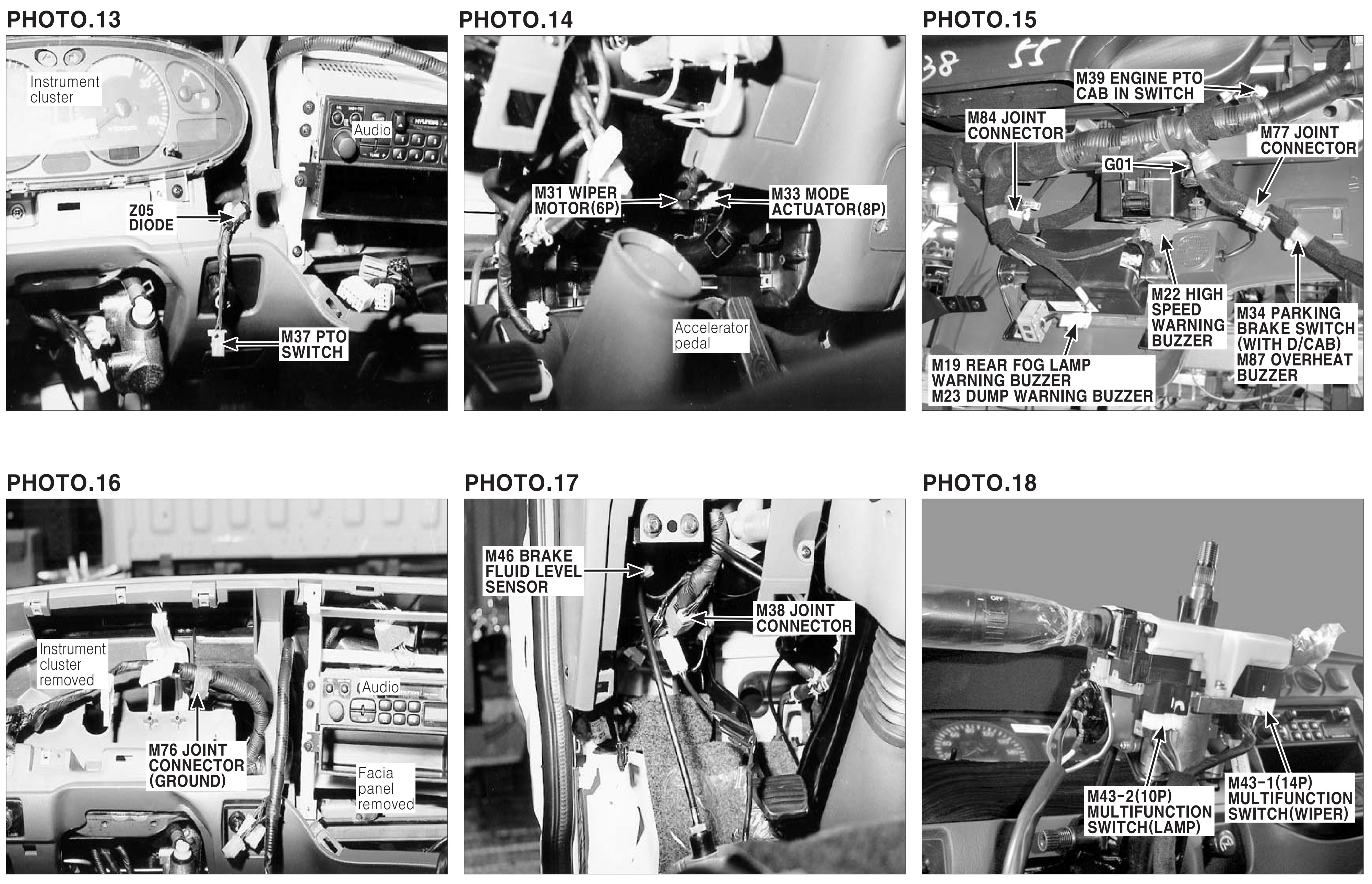
Photo 19-24.
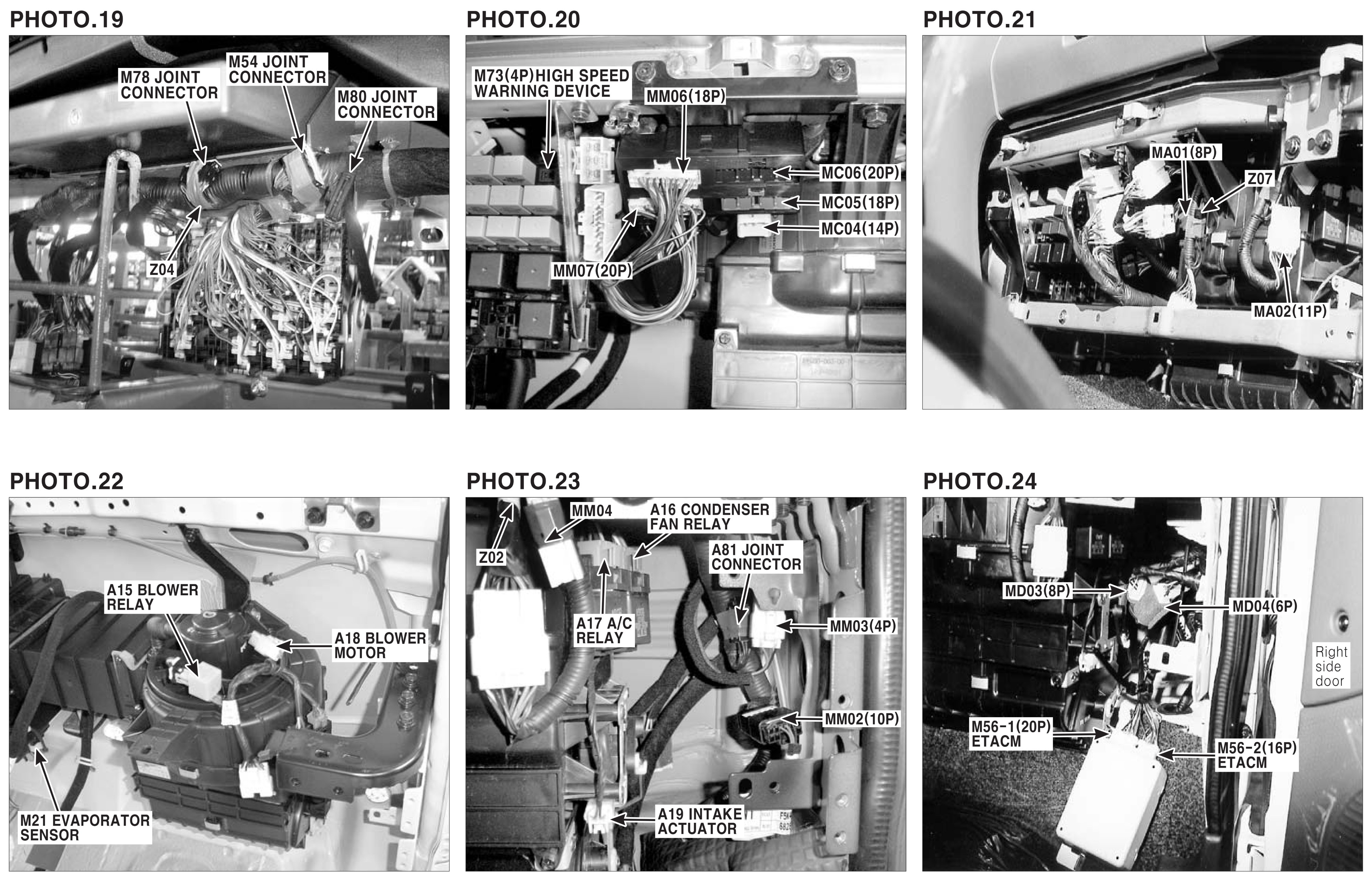
Photo 25-30.
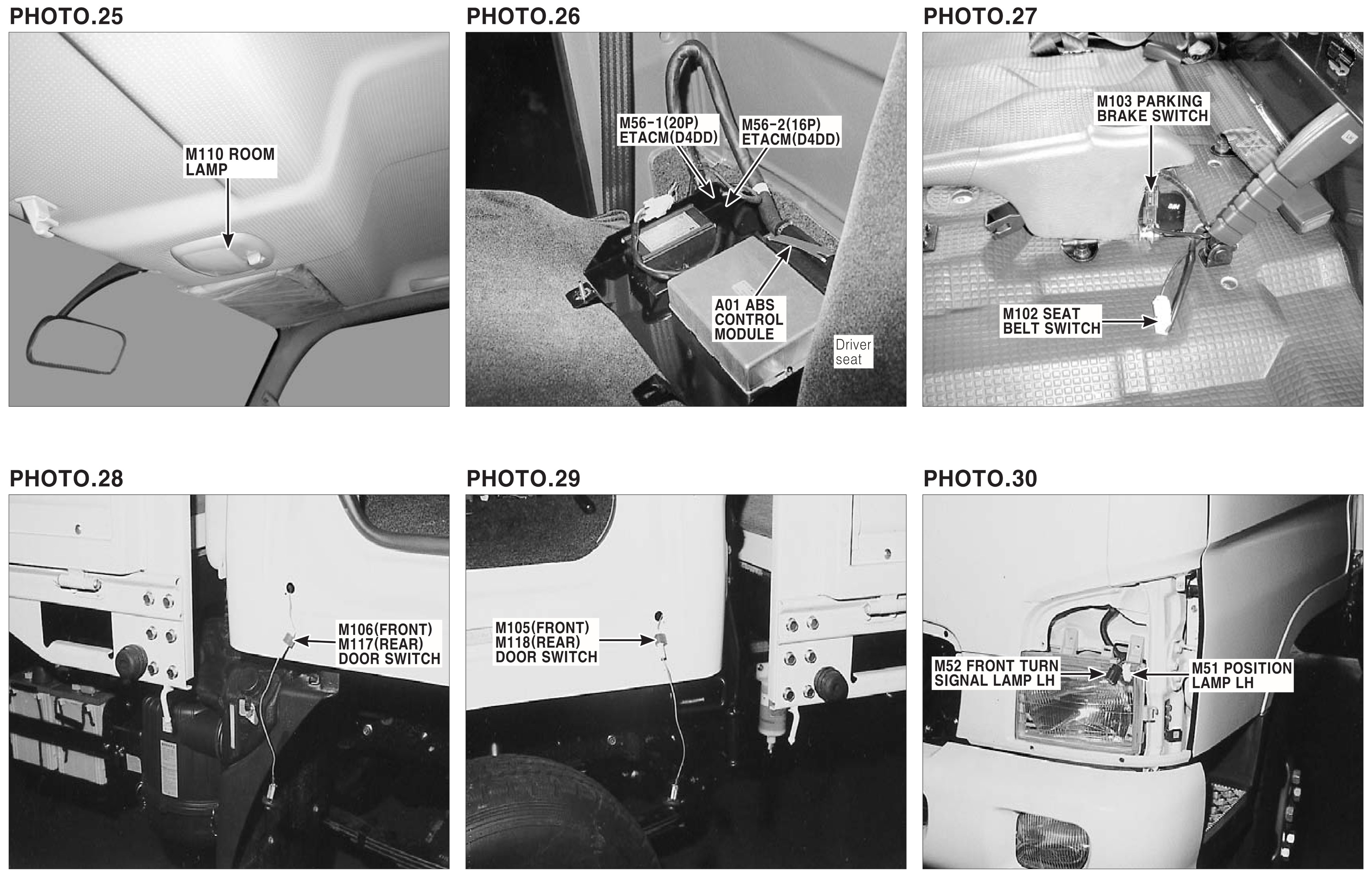
Photo 31-36.
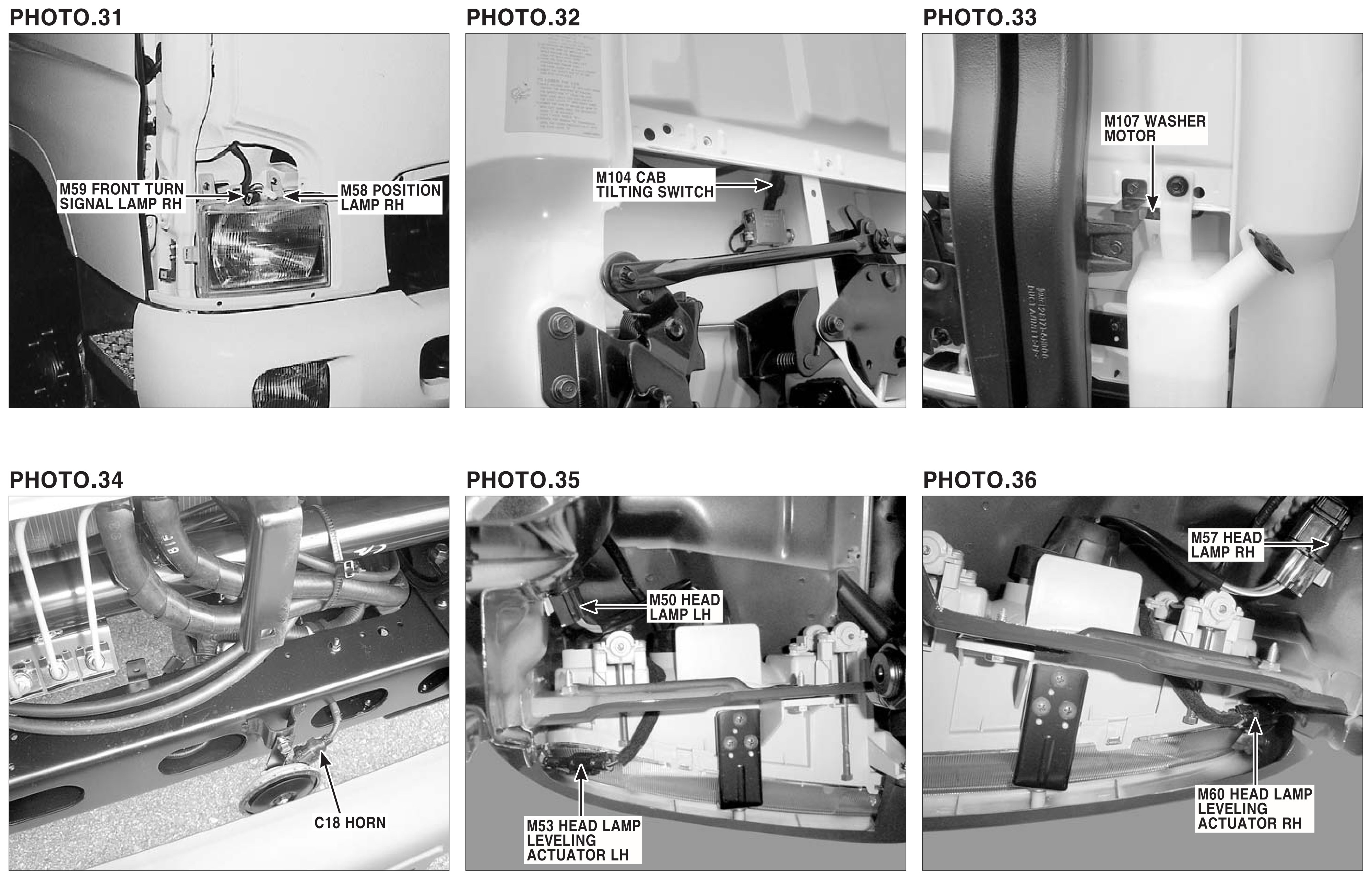
Photo 37-42.
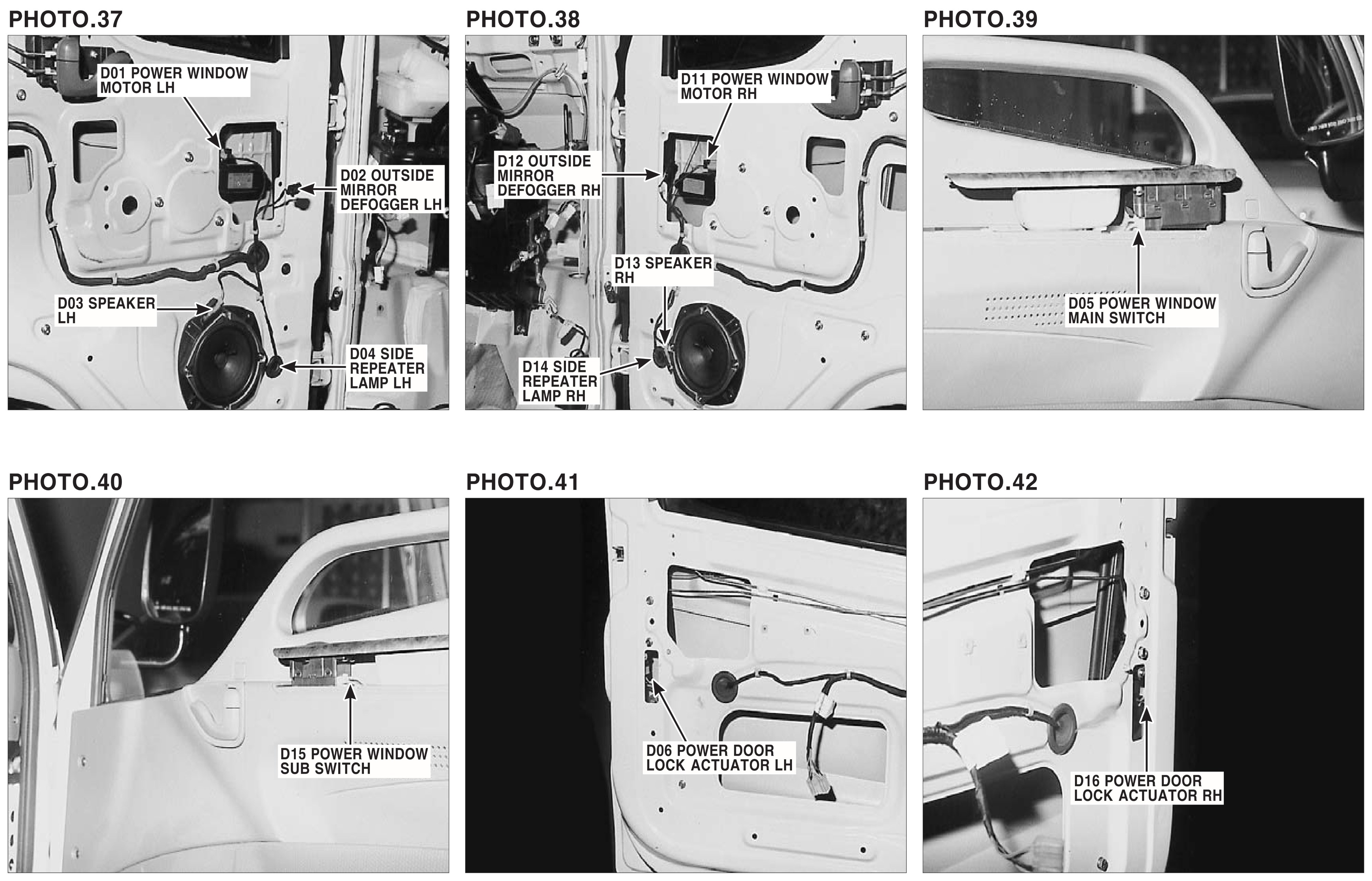
Photo 43-48.
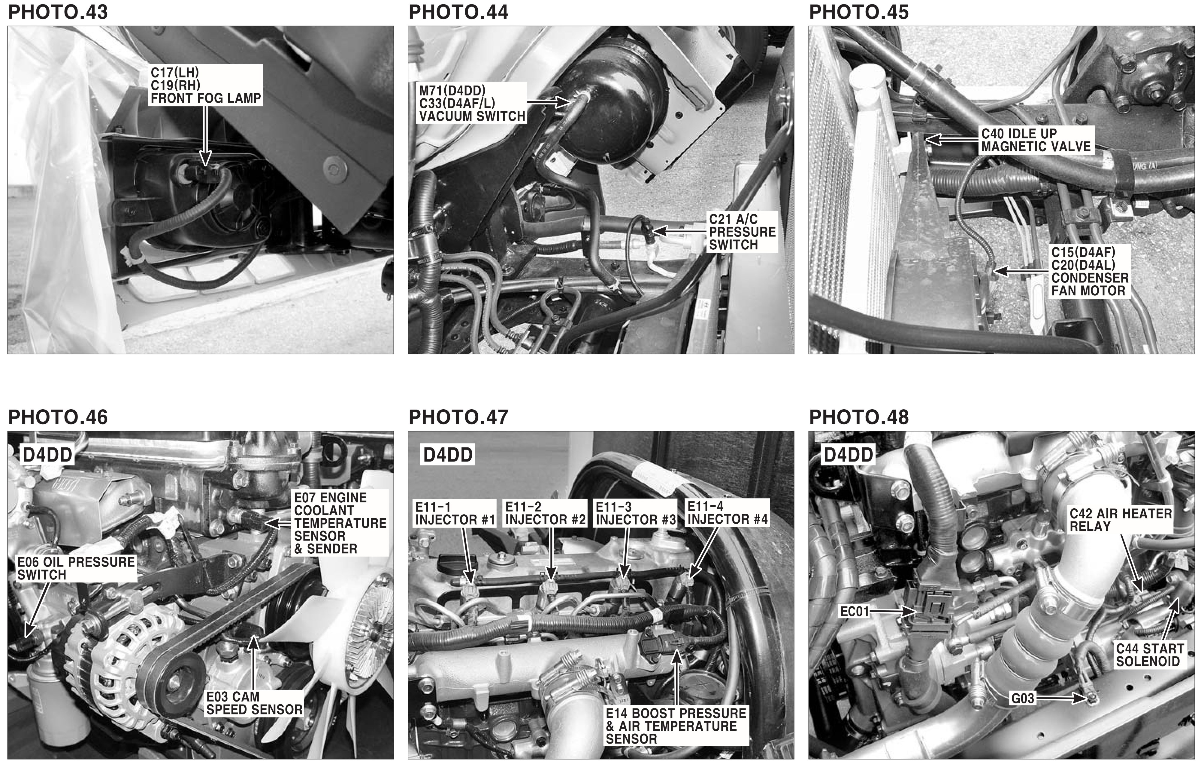
Photo 49-54.
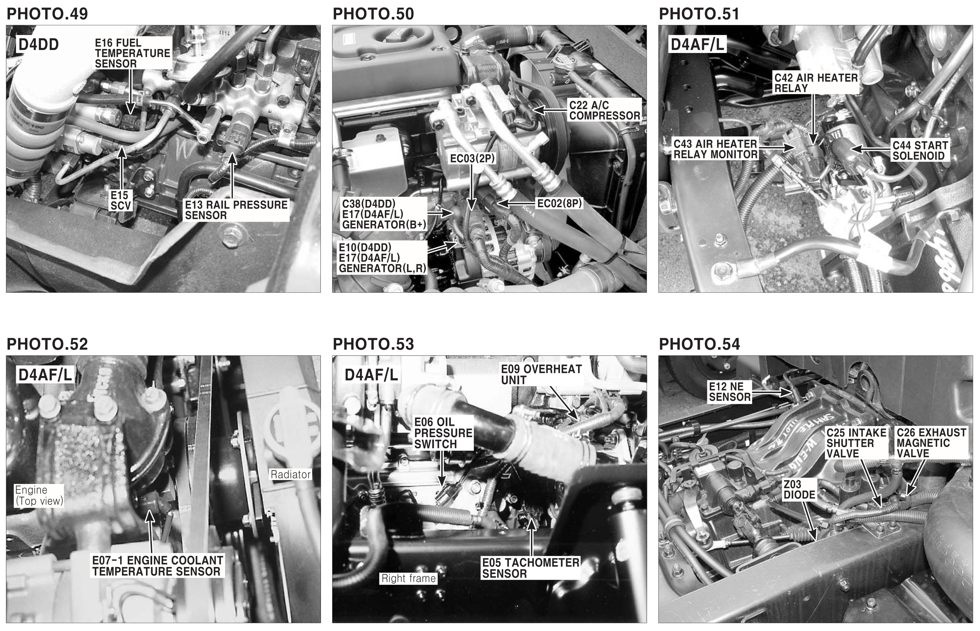
Photo 55-60.
Photo 61-66.
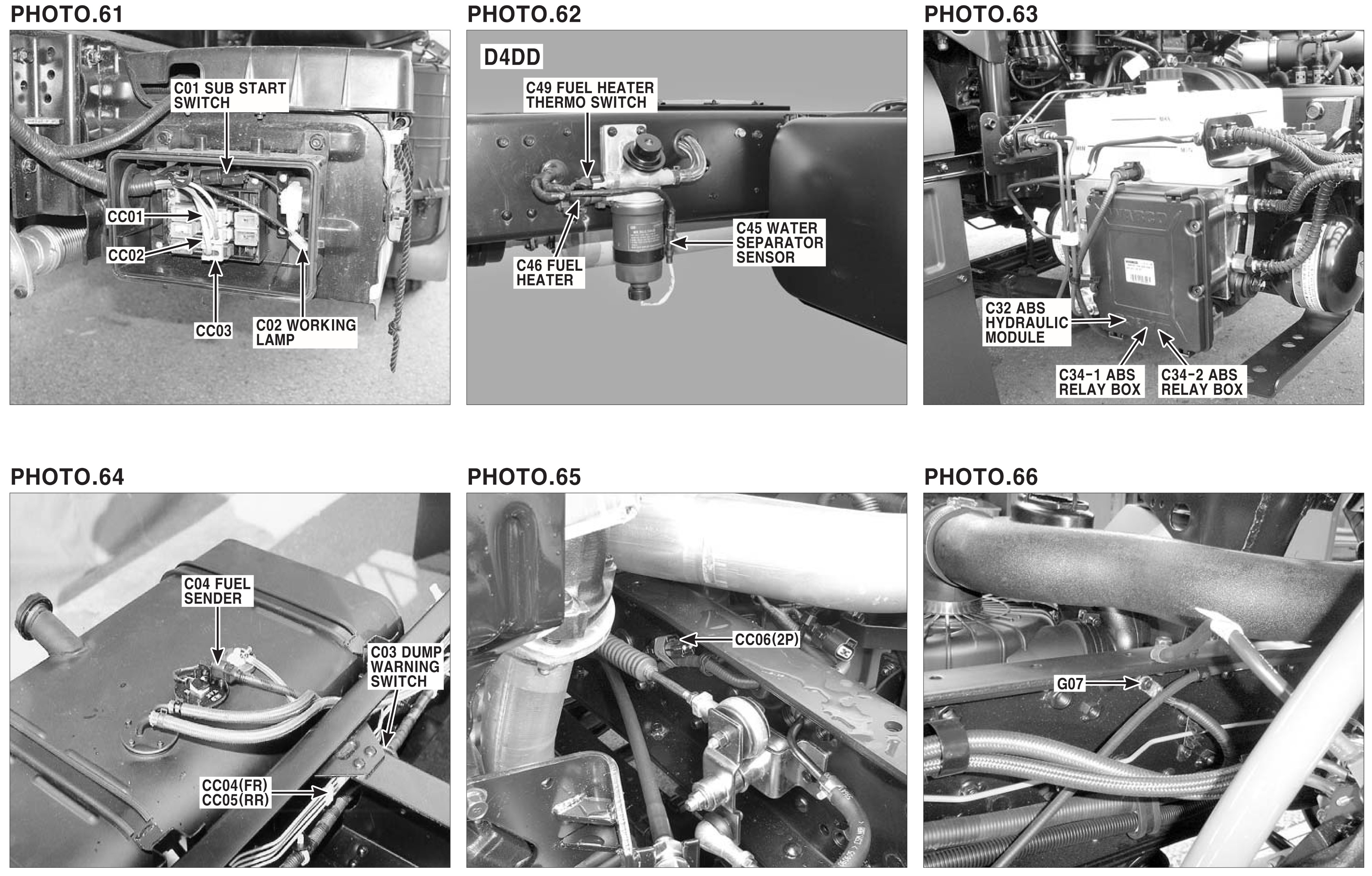
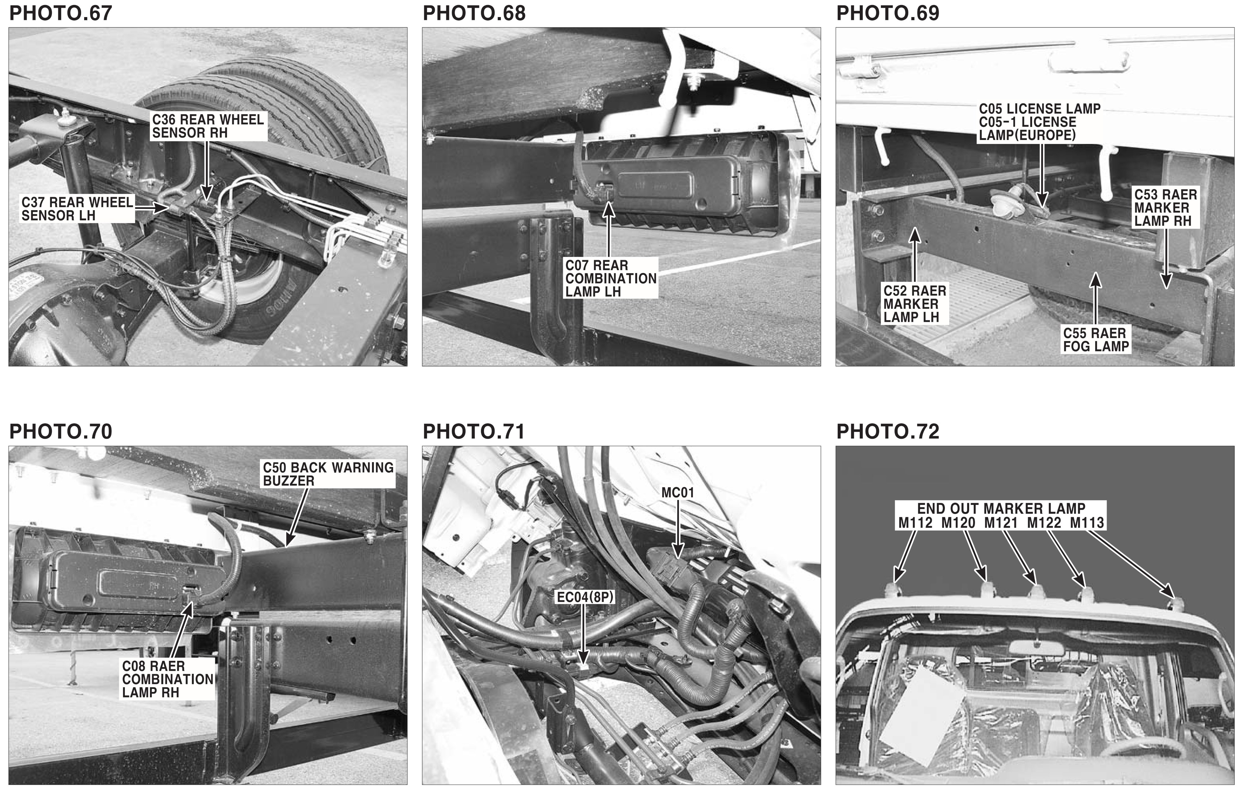
Photo 67-72.

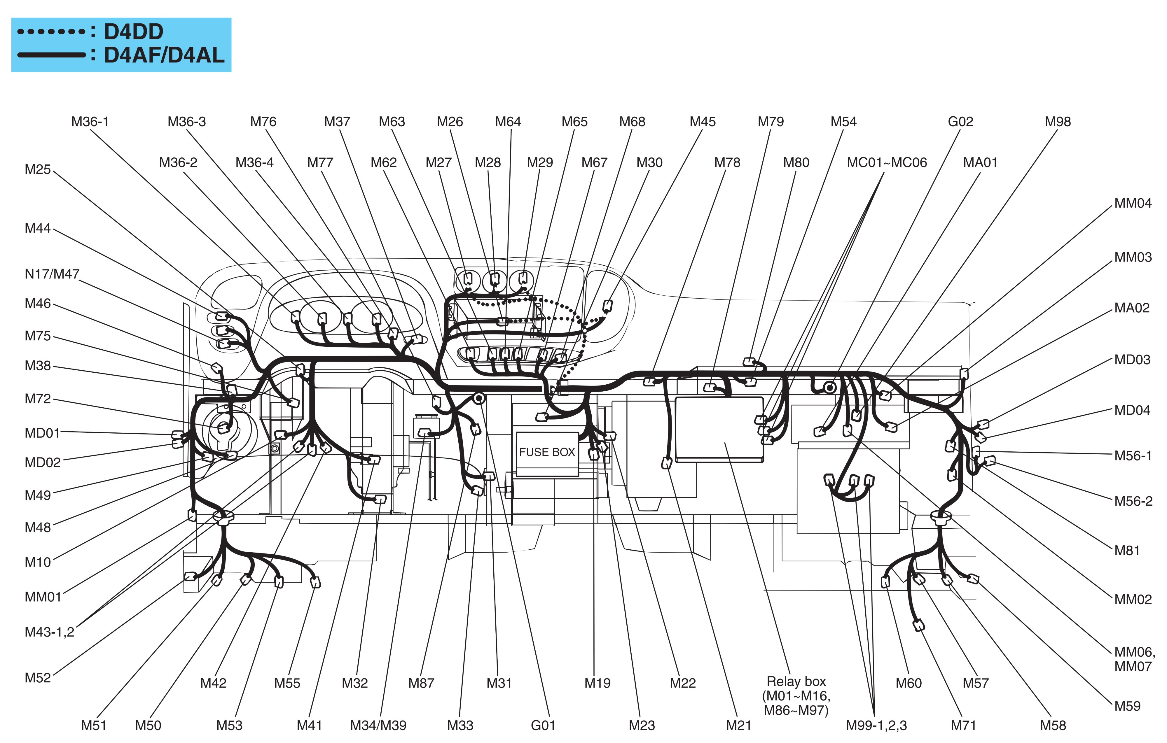
Main harness.
М01 – Front fog lamp relay;
M02 – Tail lamp relay;
M04 – Power window relay;
M05 – Power door lock relay;
M06 – Power door unlock relay;
M07 – Outside mirror defogger relay;
M08 – PTO relay;
M09 – Dump relay;
M10 – Flasher unit;
M11 – Wiper relay (High);
M12 – Wiper relay (Low);
M13 – Head lamp relay (High);
M14 – Head lamp relay (Low);
M15 – ABS relay;
M16 – Rear fog lamp relay (D4AF/D4AL);
M17 – Idle up/down switch (D4DD);
M19 – Rear fog lamp warning buzzer (D4AF/D4AL);
M21 – Evaporator sensor;
M22 – High speed warning buzzer (D4AF/D4AL);
M23 – Dump warning buzzer;
M24 – Tachograph (Electronic) (D4AF/D4AL);
M26 – Audio;
M27 – Blower switch;
M28 – Intake switch;
M29 – Mode switch;
M30 – Ashtray ILL.;
M31 – Wiper motor;
M32 – Accelerator pedal position switch;
M33 – Mode actuator;
M34 – Parking brake switch (With double cab) (D4AF/D4AL);
M36-1 – Instrument cluster;
M36-2 – Instrument cluster;
M36-3 – Instrument cluster;
M36-4 – Instrument cluster;
M37 – PTO switch;
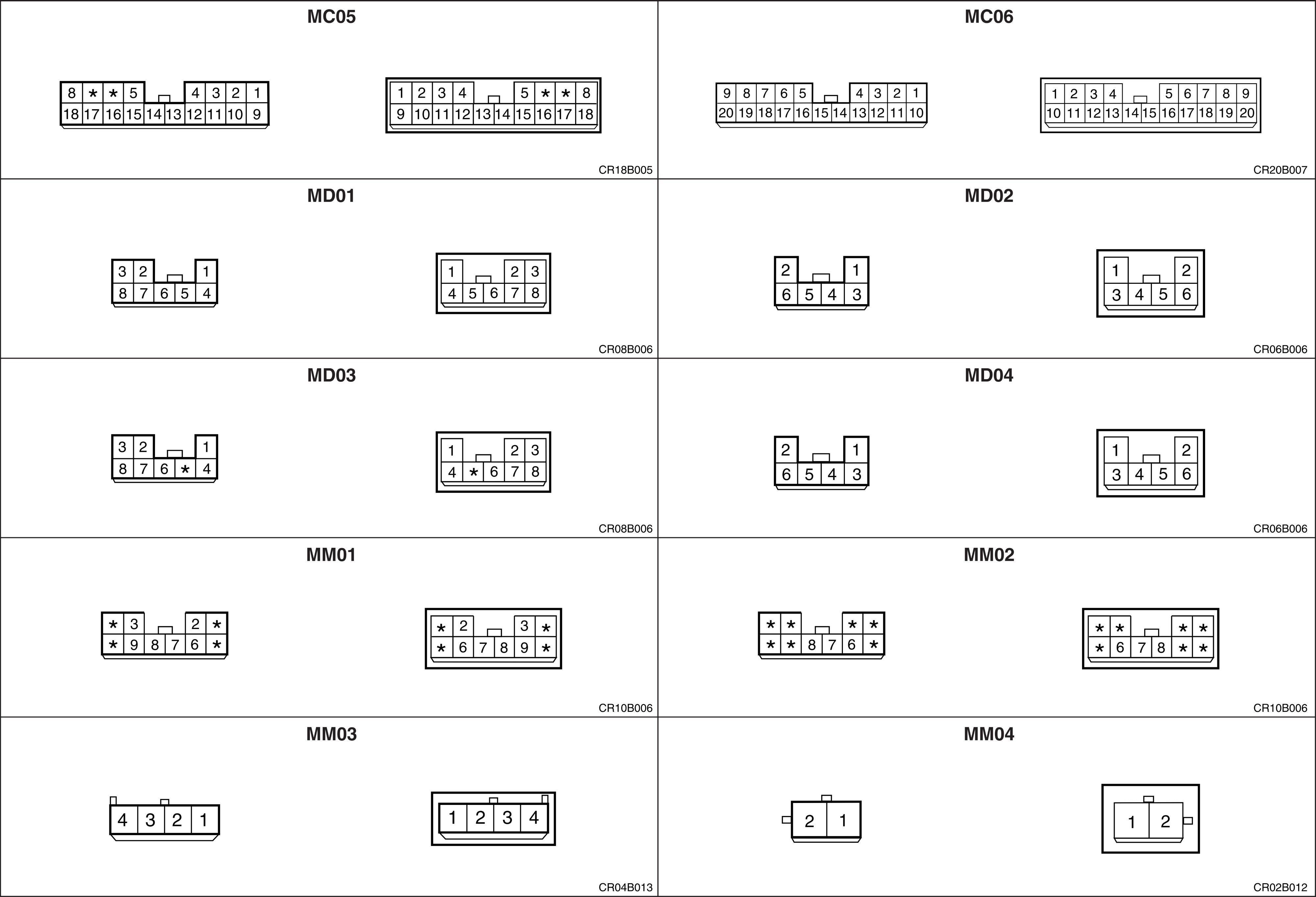
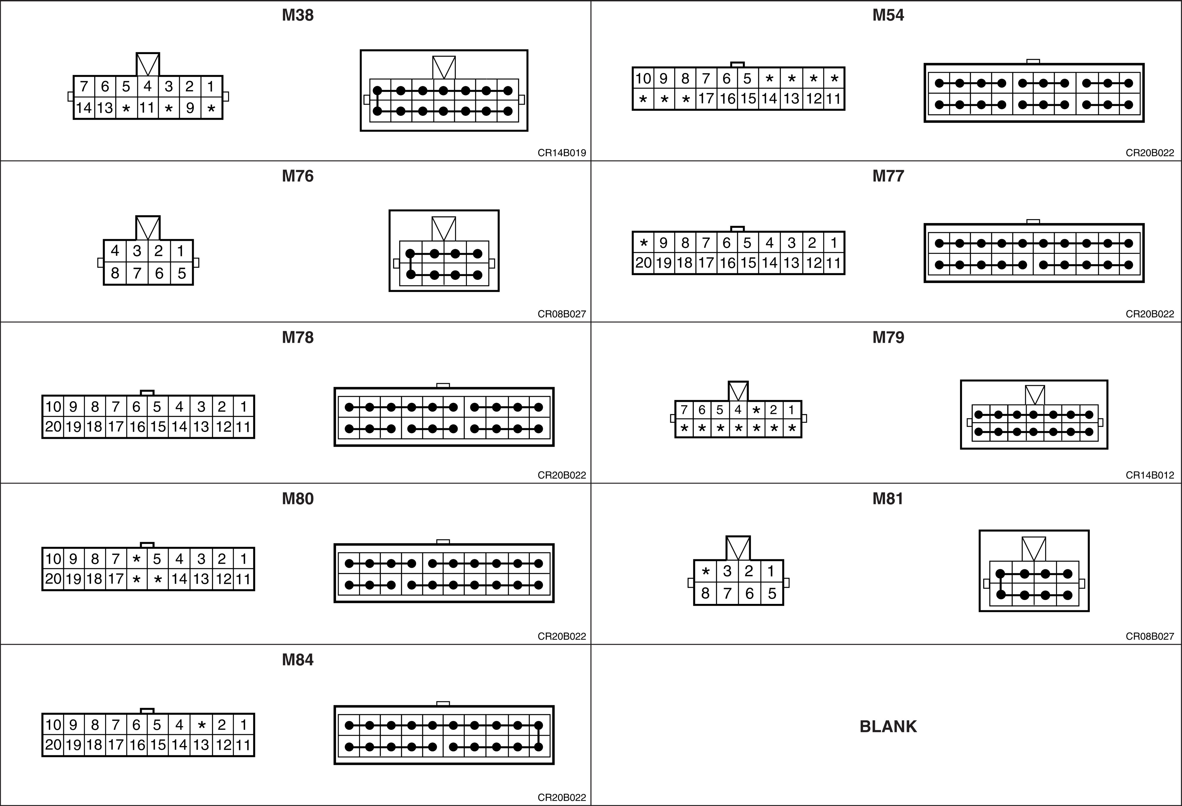
M38 – Joint connector;
M39 – Engine PTO cab in switch (D4DD);
M41 – Stop lamp switch;
M42 – Ignition switch;
М43-1 – Multifunction switch (Wiper);
M43-2 – Multifunction switch (Lamp);
M44 – Head lamp leveling switch (D4AF/D4AL);
M45 – Tachograph (Cassette type);
M46 – Brake fluid level sensor;
M47 – Cold start switch (D4AF/D4AL);
M48 – PTO clutch pedal position switch (D4AF/D4AL);
M49 – Exhaust brake clutch pedal position switch;
M50 – Head lamp LH;
M51 – Position lamp LH;
M52 – Front turn signal lamp LH;
M53 – Head lamp leveling actuator LH (D4AF/D4AL);
M54 – Joint connector;
M56-1 – ETACM (D4AF/D4AL);
M56-2 – ETACM (D4AF/D4AL);
M57 – Head lamp RH;
M58 – Position lamp RH;
M59 – Front turn signal lamp RH;
M60 – Head lamp leveling actuator RH (D4AF/D4AL);
M62 – Hazard switch;
M63 – Front fog lamp switch;
M64 – A/C switch;
M65 – Defogger switch;
M67 – Rear fog lamp switch (D4AF/D4AL);
M68 – Cigarette lighter;
M71 – Vacuum switch (D4DD);
M72 – Data link connector;
M73 – High speed warning device (D4AF/D4AL);
M75 – Working lamp switch;
M76 – Joint connector;
M77 – Joint connector;
M78 – Joint connector;
M79 – Joint connector;
M80 – Joint connector;
М81 – Joint connector;
M84 – Joint connector;
M86 – Rear fog indicator relay (D4AF/D4AL);
M87 – Overheat buzzer (D4AF/D4AL);
M88 – Horn relay (D4DD);
M90 – Fuel heater relay (D4DD);
M91 – Engine ECM relay (D4DD);
M93 – Exhaust brake relay (D4DD);
M94 – Glow relay (D4DD);
M97 – Overheat buzzer relay (D4AF/D4AL);
M99-1 – Main ECM (D4DD);
M99-2 – Main ECM (D4DD);
M99-3 – Main ECM (D4DD);
MA01 – Connection With A.B.S Harness;
MA02 – Connection With AIR CON Harness;
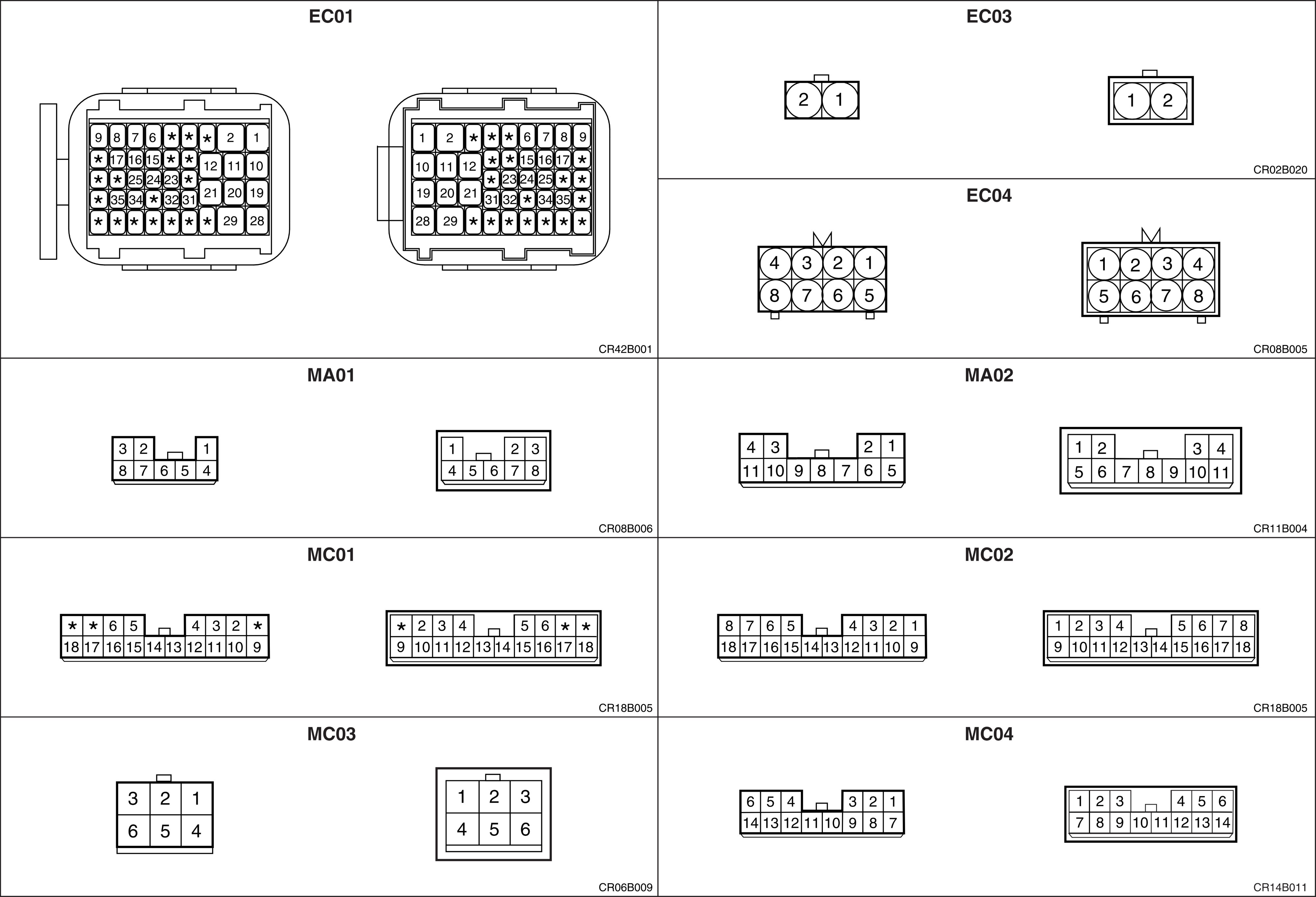
MC01 – Connection With CHASSIS Harness (D4AF/D4AL);
MC02 – Connection With CHASSIS Harness (D4AF/D4AL);
MC03 – Connection With CHASSIS Harness;
MC04 – Connection With CHASSIS Harness (D4DD);
MC05 – Connection With CHASSIS Harness (D4DD);
MC06 – Connection With CHASSIS Harness (D4DD);
MD01 – Connection With DOOR LH Harness;
MD02 – Connection With DOOR LH Harness;
MD03 – Connection With DOOR RH Harness;
MD04 – Connection With DOOR RH Harness;
MM01 – Connection With FLOOR LH Harness;
MM02 – Connection With FLOOR RH Harness;
MM03 – Connection With ROOF Harness (D4AF/D4AL);
MM04 – Connection With MAIN (JUMP) Harness (D4AF/D4AL);
MM06 – Connection With FLOOR CENTER Harness (D4DD);
MM07 – Connection With FLOOR CENTER Harness (D4DD);
G01 – Ground;
G02 – Ground;
Z01 – Diode (D4AF/D4AL);
Z02 – Diode (D4AF/D4AL);
Z04 – Diode (D4AF/D4AL);
Z05 – Diode;
Z07 – Diode (D4DD).
(D4AF/D4AL).
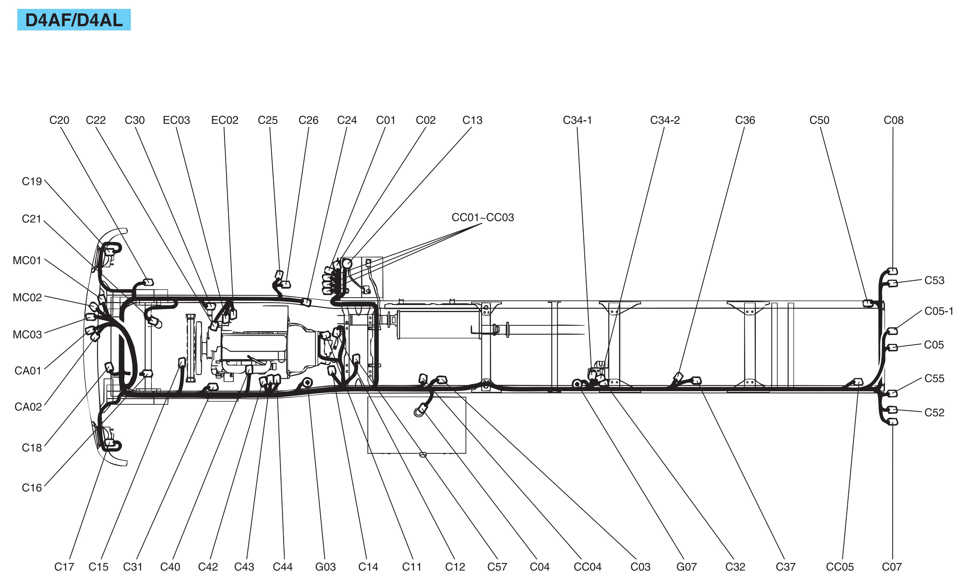
Chassis harness (D4AF/D4AL).
С01 – Sub start switch;
C02 – Working lamp;
C03 – Dump warning switch;
C04 – Fuel sender;
C05 – License lamp;
C05-1 – License lamp (Europe);
C07 – Rear combination lamp LH;
C08 – Rear combination lamp RH;
C11 – Neutral switch;
C12 – Back-up lamp switch;
C13 – Battery;
C14 – PTO control switch;
C15 – Condenser fan motor (D4AF);
C17 – Front fog lamp LH;
C18 – Horn;
C19 – Front fog lamp RH;
C20 – Condenser fan motor (D4AL);
C21 – A/C pressure switch;
C22 – A/C compressor;
C24 – PTO magnetic valve;
C25 – Intake shutter valve;
C26 – Exhaust magnetic valve;
C30 – Front wheel sensor RH;
C31 – Front wheel sensor LH;
C32 – ABS hydraulic module;
C33 – Vacuum switch;
C34-1 – ABS relay box;
C34-2 – ABS relay box;
C36 – Rear wheel sensor RH;
C37 – Rear wheel sensor LH;
C40 – Idle up magnetic valve;
C42 – Air heater relay;
C43 – Air heater relay;
C44 – Start solenoid;
C50 – Back warning buzzer;
С52 – Rear marker lamp LH;
C53 – Rear marker lamp RH;
C55 – Rear fog lamp;
C57 – Vehicle speed sensor;
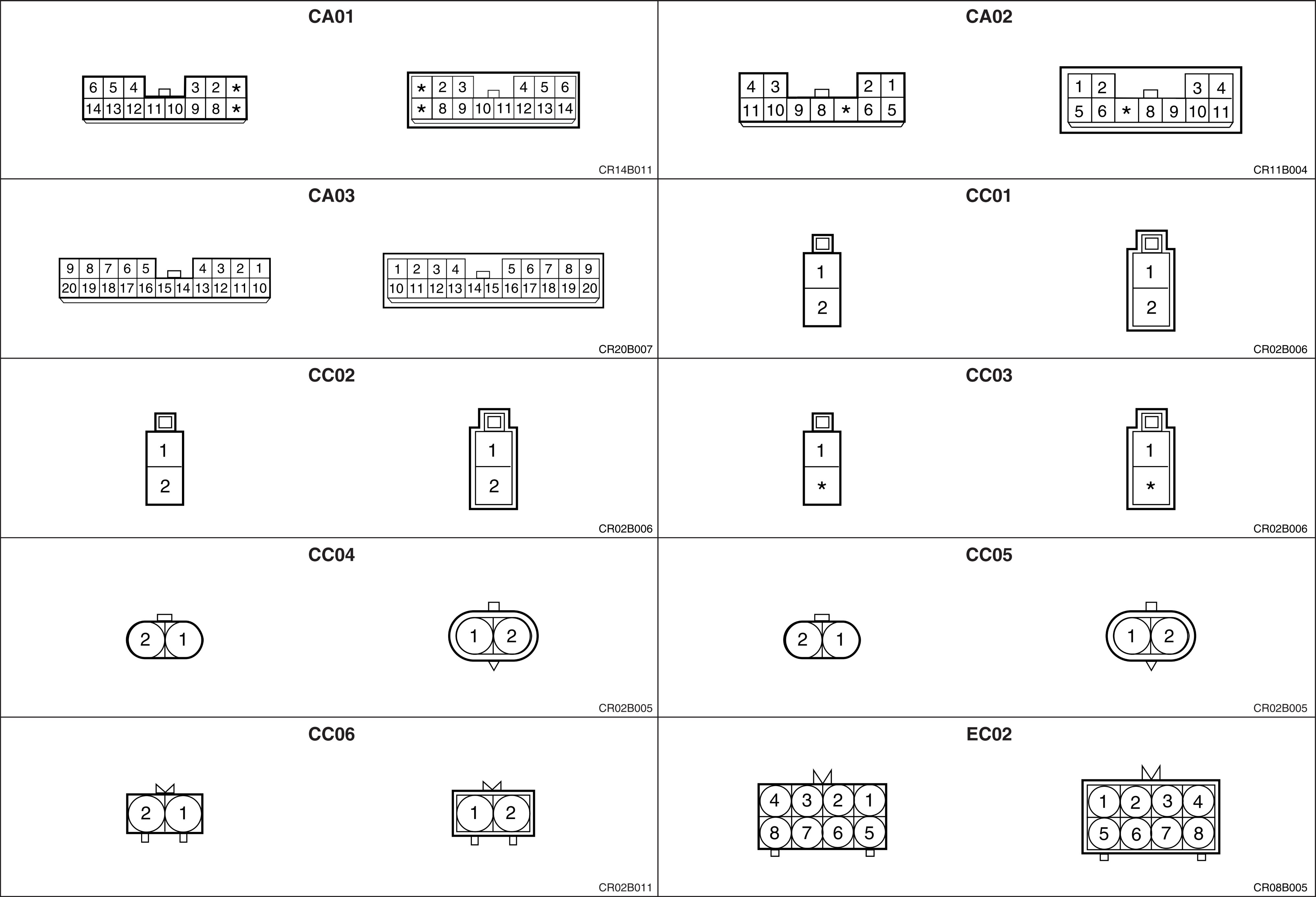
CA01 – Connection With A.B.S Harness;
CA02 – Connection With A.B.S Harness;
CC01 – Connection With Fusible Link Box;
CC02 – Connection With Fusible Link Box;
CC03 – Connection With Fusible Link Box;
CC04 – Connection With SIDE MARKER Harness4
CC05 – Connection With SIDE MARKER Harness;
EC02 – Connection With ENGINE RH Harness;
EC03 – Connection With ENGINE Harness;
MC01 – Connection With MAIN Harness;
MC02 – Connection With MAIN Harness;
MC03 – Connection With MAIN Harness;
G03 – Ground;
G07 – Ground;
Z03 – Diode.
Side marker harness (D4AF/D4AL).
C70 – Front outside marker lamp LH;
C72 – Front outside marker lamp RH;
C73 – Rear outside marker lamp LH;
C74 – Rear outside marker lamp RH;
CC04 – Connection With CHASSIS Harness;
CC05 – Connection With CHASSIS Harness.
D4DD.
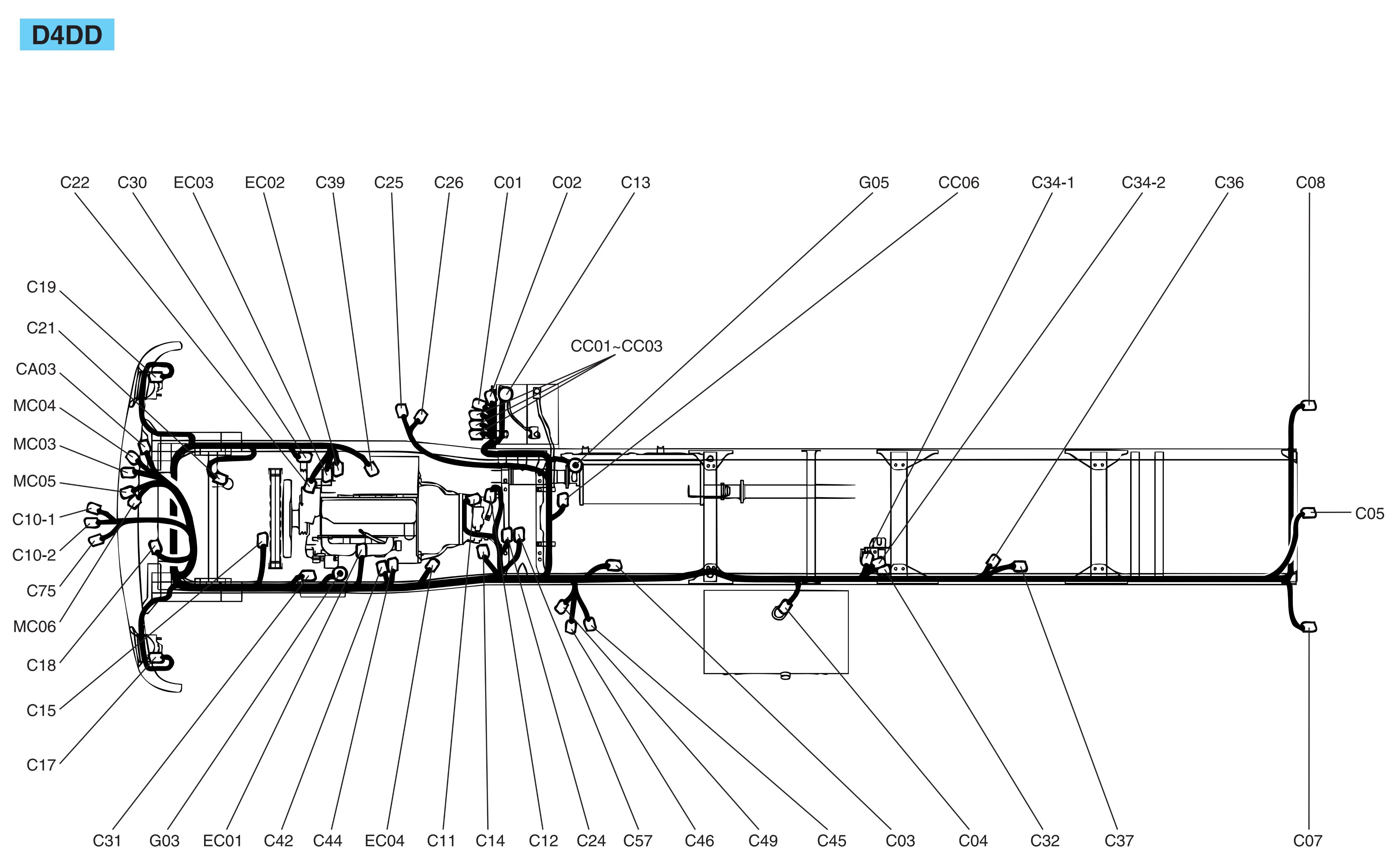
Chassis harness (D4DD).
С01 – Sub start switch;
C02 – Working lamp;
C03 – Dump warning switch;
C04 – Fuel sender;
C05 – License lamp;
C07 – Rear combination lamp LH;
C08 – Rear combination lamp RH;
C10-1 – Engine ECM;
C10-2 – Engine ECM;
C11 – Neutral switch;
C12 – Back-up lamp switch;
C13 – Battery;
C14 – PTO control switch;
C15 – Condenser fan motor;
C17 – Front fog lamp LH;
C18 – Horn;
C19 – Front fog lamp RH;
C21 – A/C pressure switch;
C22 – A/C compressor;
C24 – PTO magnetic valve;
C25 – Intake shutter valve (With double cab);
C26 – Exhaust magnetic valve (With double cab);
C30 – Front wheel sensor RH;
C31 – Front wheel sensor LH;
C32 – ABS hydraulic module;
C34-1 – ABS relay box;
C34-2 – ABS relay box;
C36 – Rear wheel sensor RH;
C37 – Rear wheel sensor LH;
C39 – Generator;
C42 – Air heater relay;
C44 – Start solenoid;
C45 – Water separator sensor;
C46 – Fuel heater;
C49 – Fuel heater thermo switch;
С57 – Vehicle speed sensor;
C75 – Can tool;
CA03 – Connection With A.B.S Harness;
CC01 – Connection With Fusible Link Box;
CC02 – Connection With Fusible Link Box;
CC03 – Connection With Fusible Link Box;
CC06 – Connection With EXH M/V Harness;
EC01 – Connection With ENGINE LH Harness;
EC02 – Connection With ENGINE RH Harness;
EC03 – Connection With ENGINE Harness;
EC04 – Connection With ENGINE PTO Harness;
MC03 – Connection With MAIN Harness;
MC04 – Connection With MAIN Harness;
MC05 – Connection With MAIN Harness;
MC06 – Connection With MAIN Harness;
G03 – Ground;
G05 – Ground;
Z03 – Diode (With double cab).
EXH M/V harness (W/O double cab).
C25 – Intake shutter valve;
C26 – Exhaust magnetic valve;
CC06 – Connection With CHASSIS Harness;
Z03 – Diode.
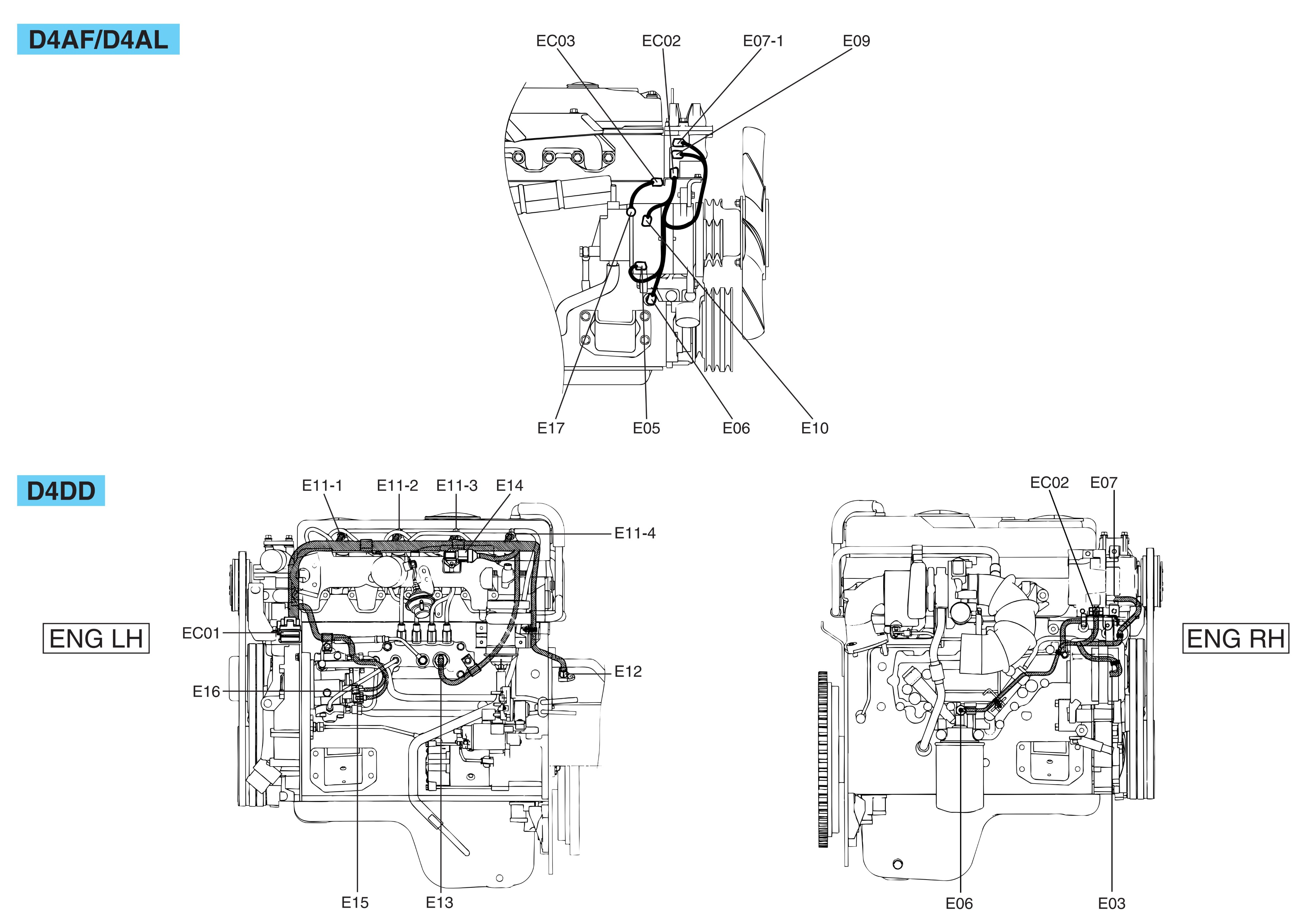
Engine harness.
E17 – Generator;
EC03 – Connection With CHASSIS Harness.
Engine harness LH (D4DD).
Е11-1 – Injector #1;
E11-2 – Injector #2;
E11-3 – Injector #3;
E11-4 – Injector #4;
E12 – N.E sensor;
E13 – Rail pressure sensor;
E14 – Boost pressure & air temperature sensor;
E15 – SCV;
E16 – Fuel temperature sensor;
EC01 – Connection With CHASSIS Harness.
Engine harness RH (D4DD).
E03 – Cam speed sensor;
E06 – Oil pressure switch;
E07 – Engine coolant temperature sensor & sender;
EC02 – Connection With CHASSIS Harness;
Engine harness RH (D4AF/D4AL).
Е05 – Tachometer sensor;
E06 – Oil pressure switch;
E07-1 – Engine coolant temperature sensor;
E09 – Overheat unit;
E10 – Generator;
EC02 – Connection With CHASSIS Harness.
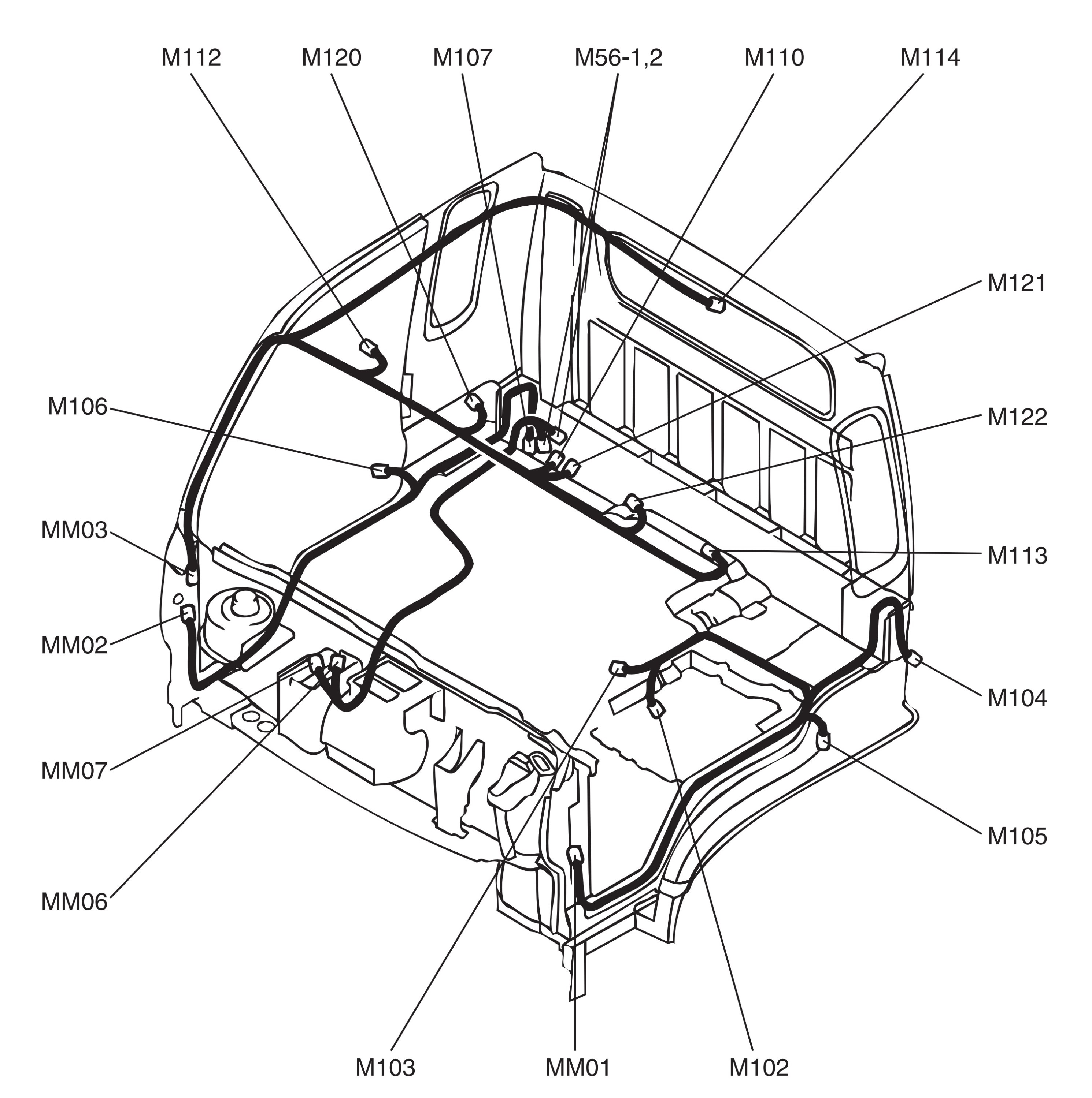
Floor harness LH.
M102 – Seat belt switch;
M103 – Parking brake switch (W/O double cab);
M104 – Cab tilting switch (W/O double cab);
M105 – Front door swtich LH;
M118 – Rear door swtich LH (With double cab);
MM01 – Connection With MAIN Harness.
Floor harness RH.
M106 – Front door swtich RH;
M107 – Washer motor;
M117 – Rear door swtich RH;
MM02 – Connection With MAIN Harness.
Floor center harness (D4DD).
M56-1 – ETACM;
M56-2 – ETACM;
MM06 – Connection With MAIN Harness;
MM07 – Connection With MAIN Harness.
Roof harness.
M110 – Front room lamp;
M112 – Endout marker lamp ‘A'(W/0 double cab);
M113 – Endout marker lamp ‘B'(W/O double cab);
M114 – Rear room lamp(With double cab);
M120 – Endout marker lamp ‘C'(W/O double cab);
M121 – Endout marker lamp ‘D'(W/0 double cab);
M122 – Endout marker lamp ‘E'(W/O double cab);
MM03 – Connection With MAIN Harness.
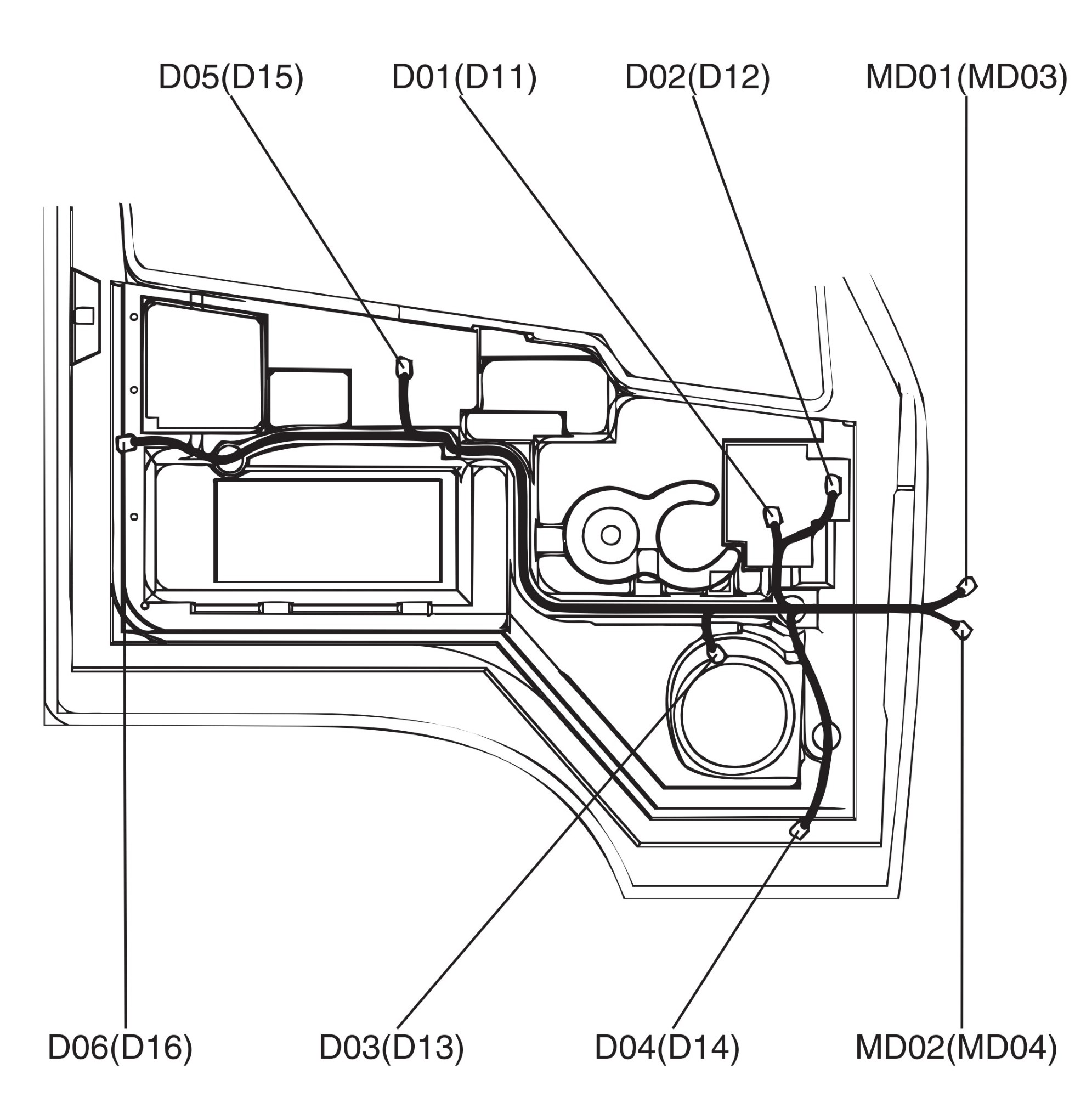
Door harness LH.
D01 – Power window motor LH;
D02 – Outside mirror defogger LH;
D03 – Speaker LH;
D04 – Side repeater lamp LH;
D05 – Power window main switch;
D06 – Power door lock actuator LH;
MD01 – Connection With MAIN Harness;
MD02 – Connection With MAIN Harness.
Door harness RH.
D11 – Power window motor RH;
D12 – Outside mirror defogger RH;
D13 – Speaker RH;
D14 – Side repeater lamp RH;
D15 – Power window sub switch;
D16 – Power door lock actuator RH;
MD03 – Connection With MAIN Harness;
MD04 – Connection With MAIN Harness.
A.B.S & air con harness.
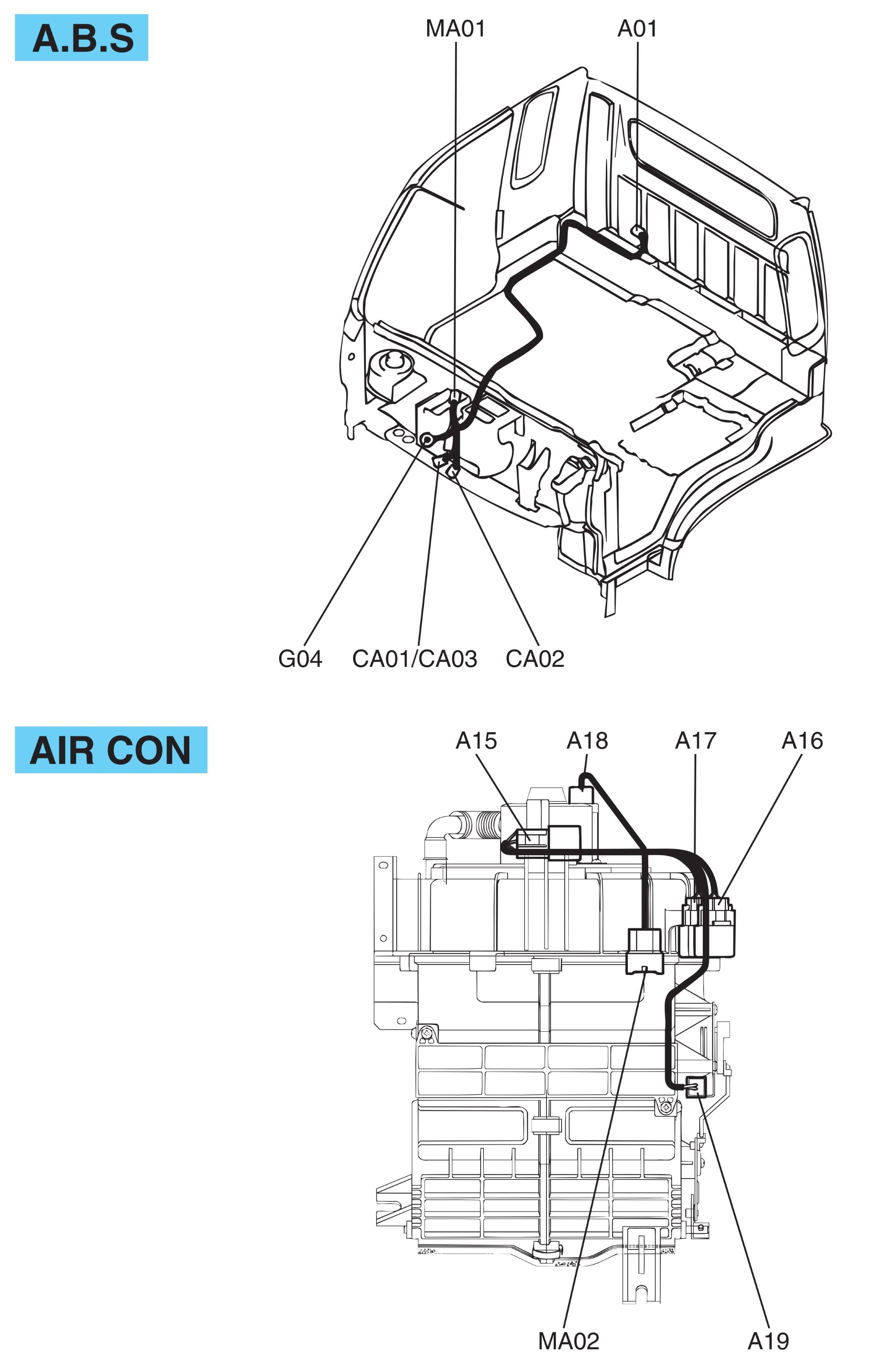
A.B.S harness (D4AF/D4AL).
A01 – ABS control module;
CA01 – Connection With CHASSIS Harness;
CA02 – Connection With CHASSIS Harness;
MA01 – Connection With MAIN Harness;
G04 – Ground.
A.B.S harness (D4DD).
A01 – ABS control module;
CA03 – Connection With CHASSIS Harness;
MA01 – Connection With MAIN Harness;
G04 – Ground.
Air con harness.
A15 – Blower relay;
A16 – Condenser fan relay;
A17 – A/C relay;
A18 – Blower motor;
A19 – Intake actuator;
MA02 Connection With MAIN Harness.
Схемы электрооборудования (другой вариант).
Обозначение цветов проводов на схемах: В – Черный; BR – Коричневый; LG – Светло-зеленый; G – Зеленый; GR – Серый; L – Синий; О – Оранжевый; Р – Розовый; R – Красный; W – Белый; Y – Желтый.
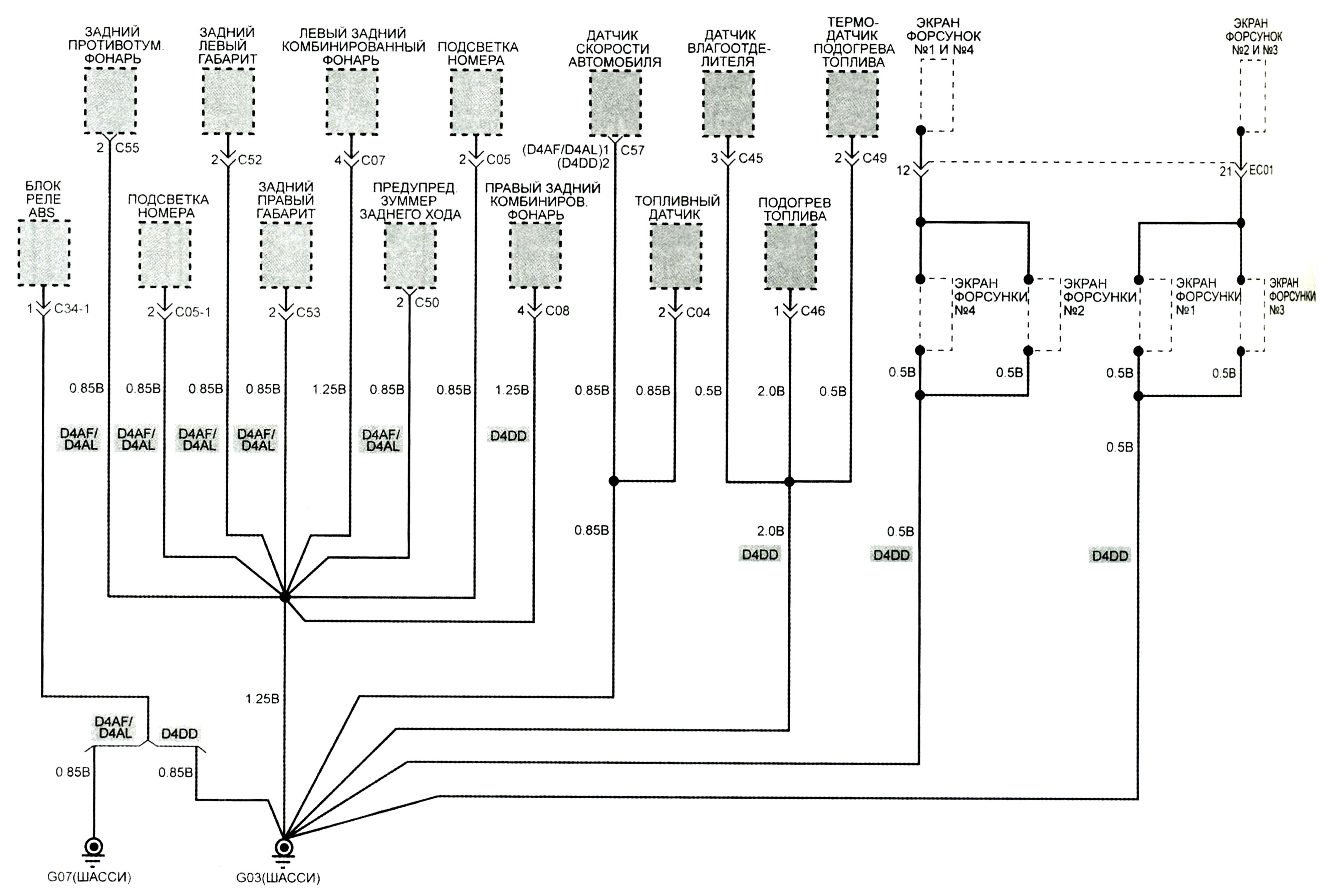
Разводка «массы».
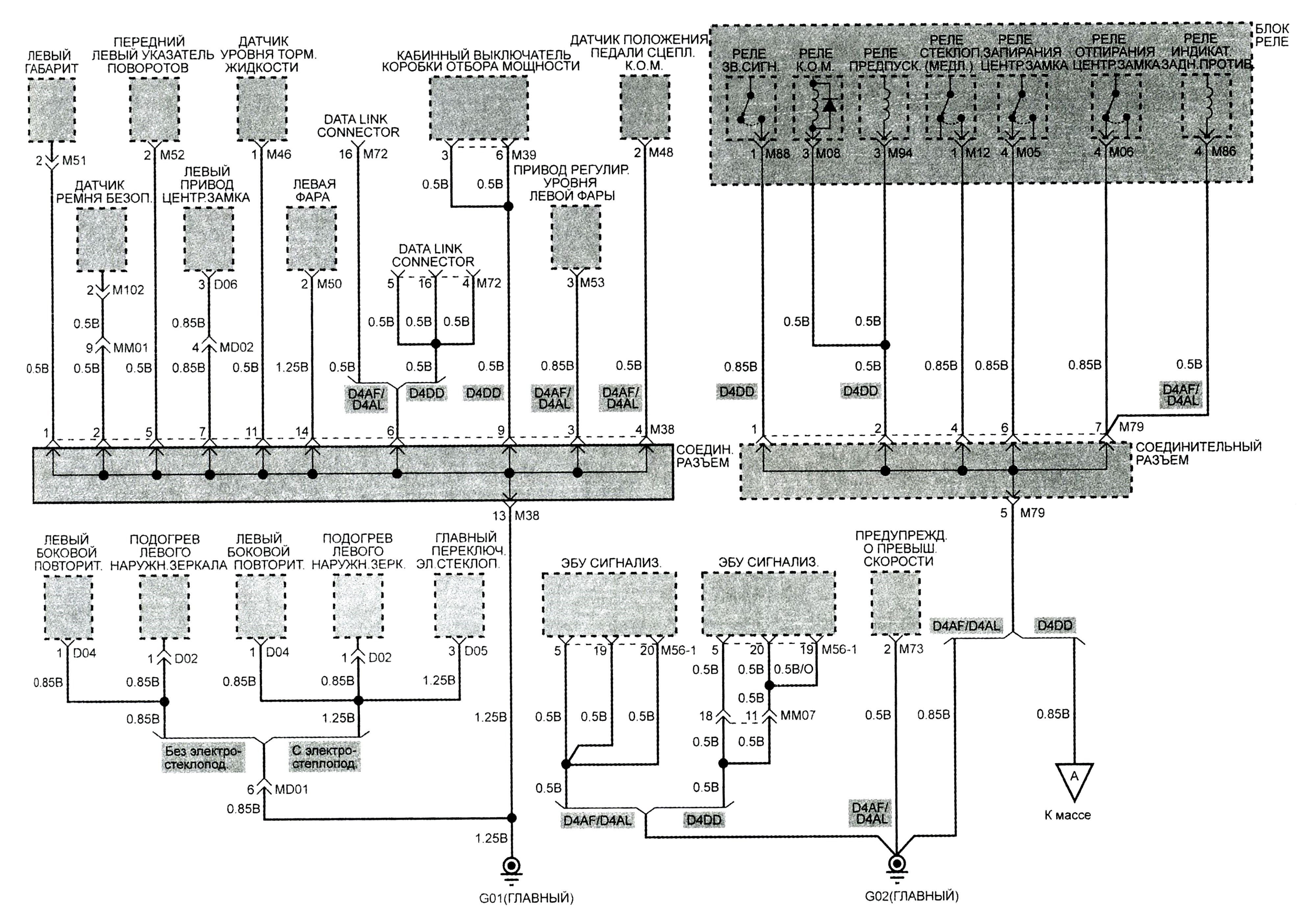
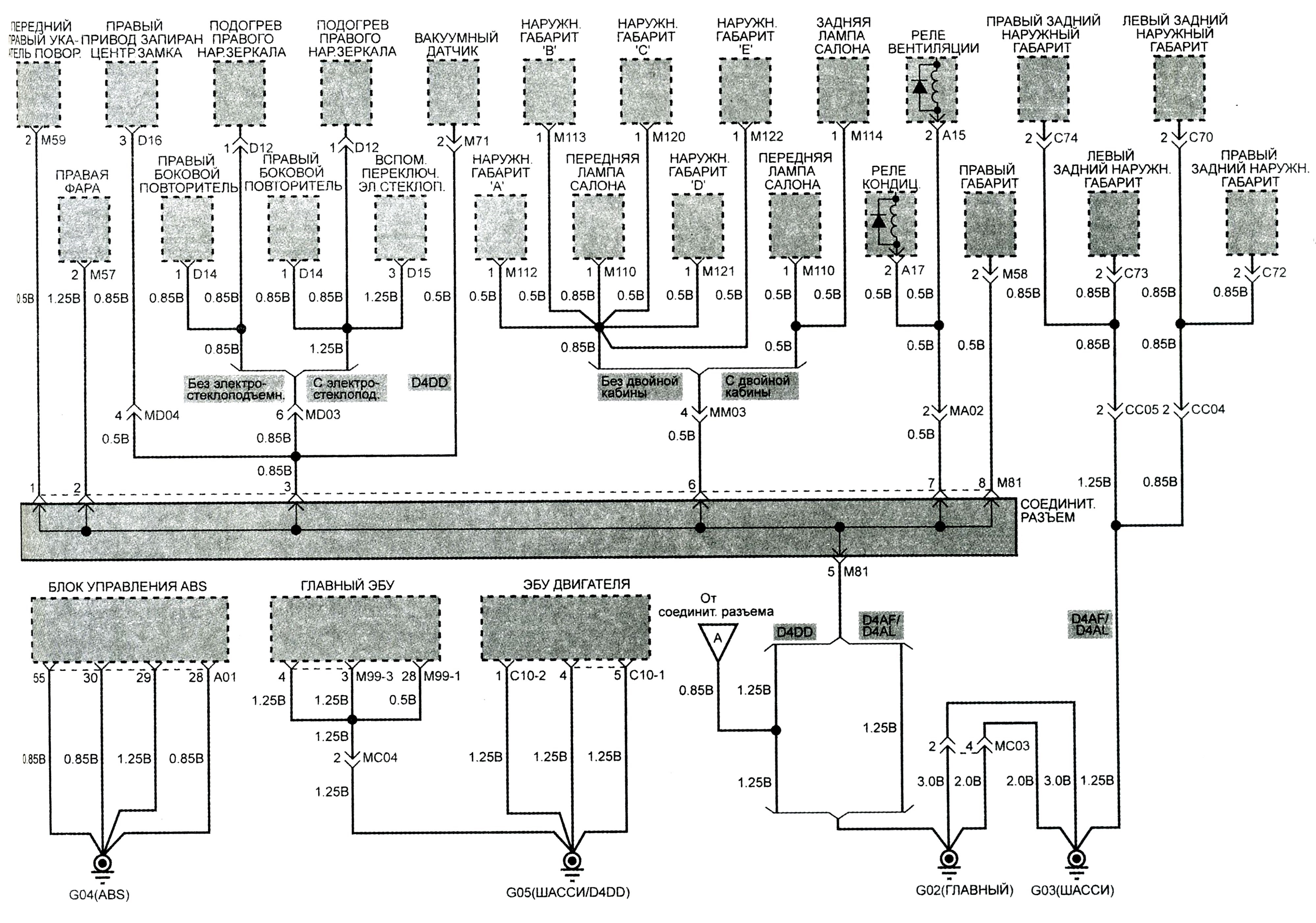
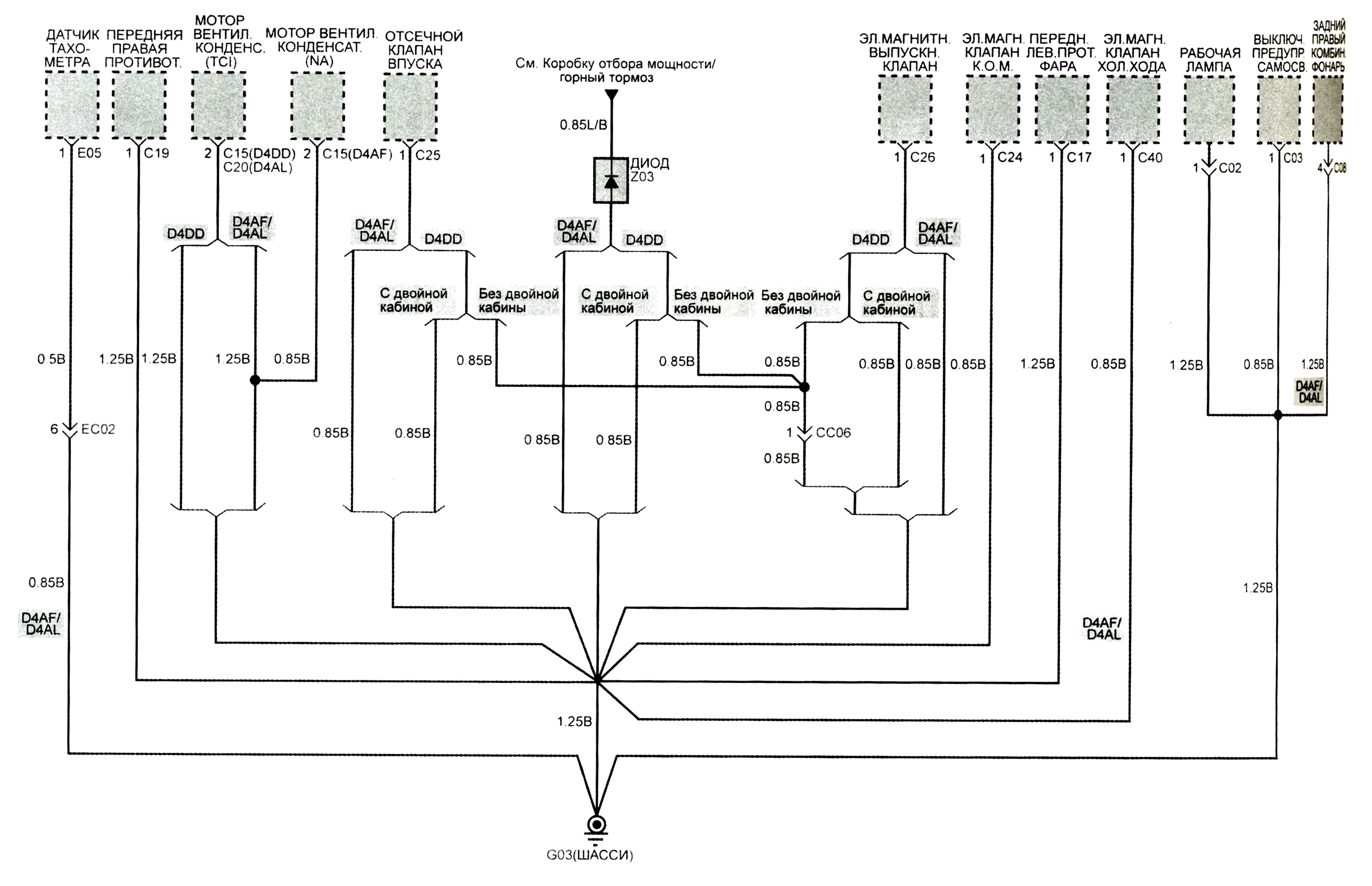
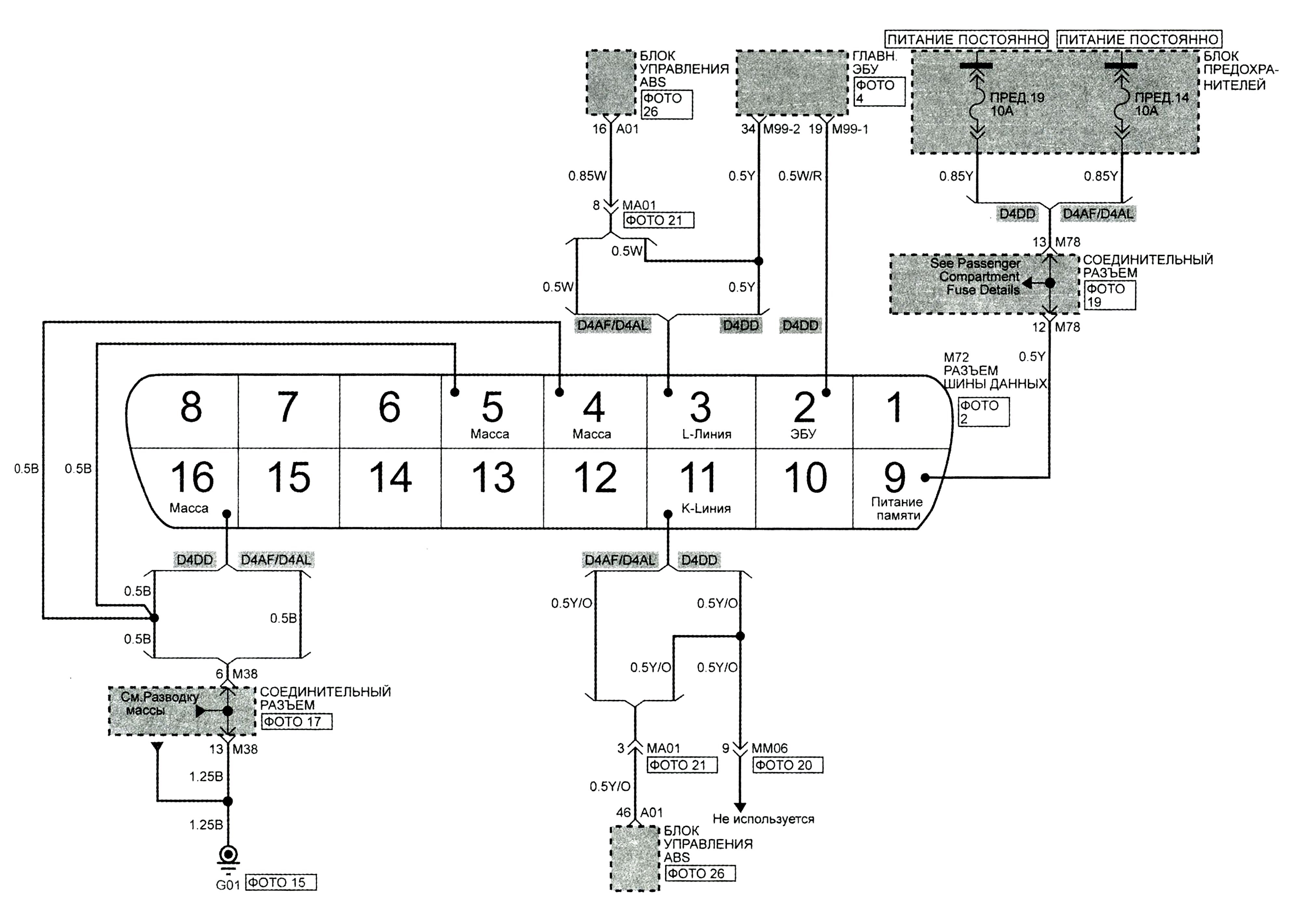
Разъём шины данных.
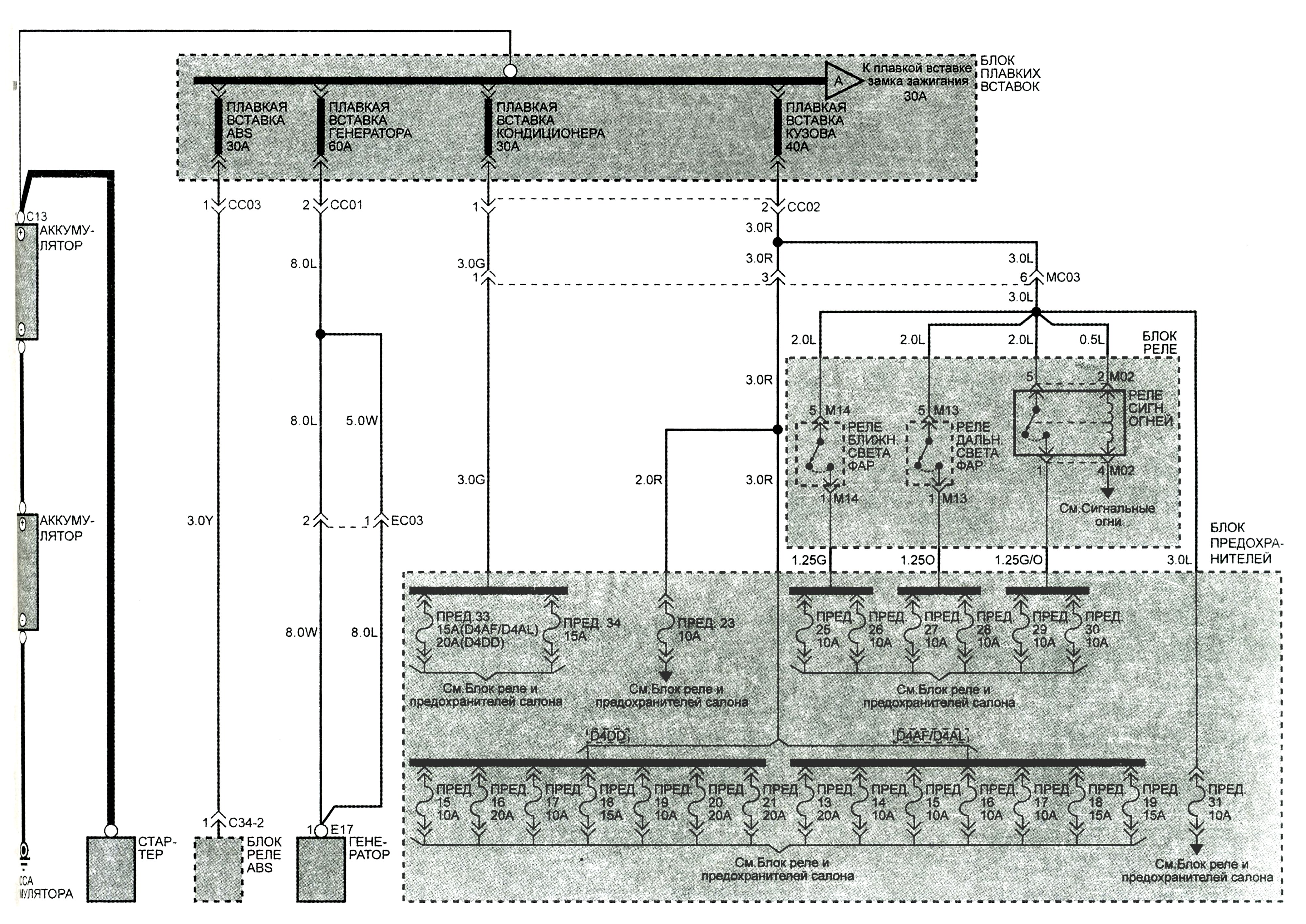
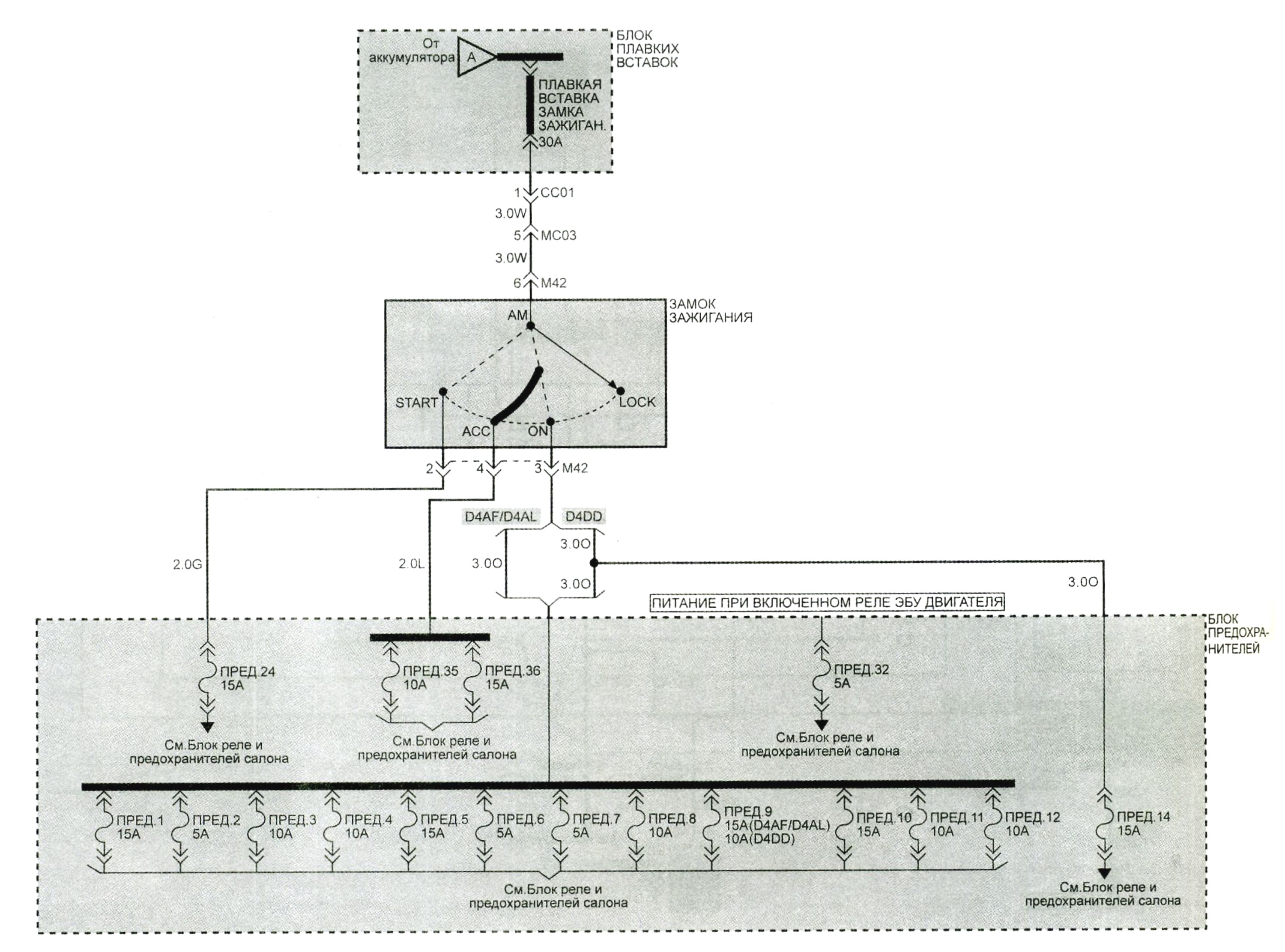
Распределение питания.
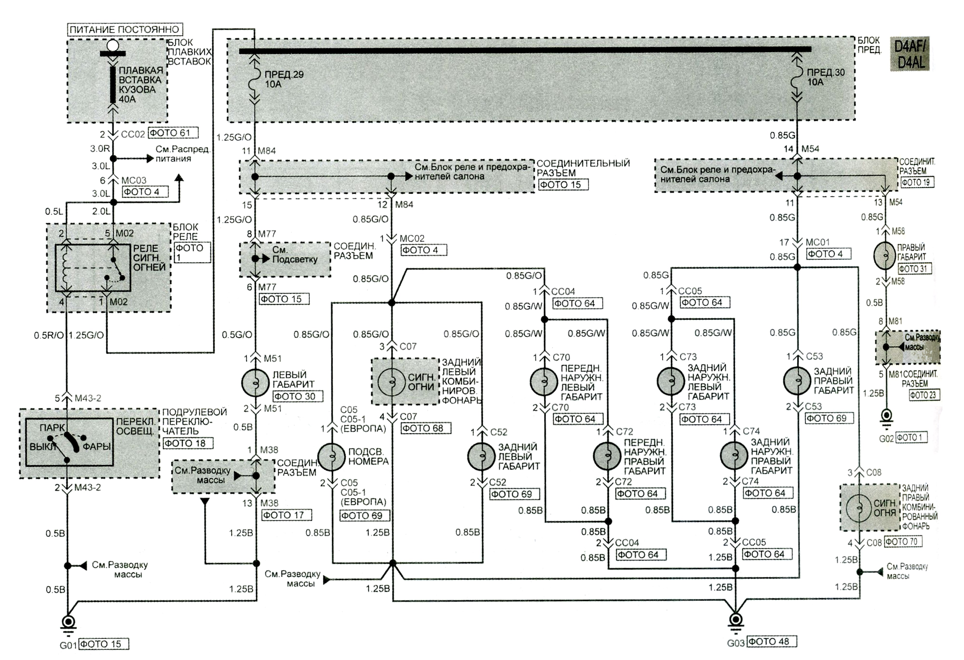
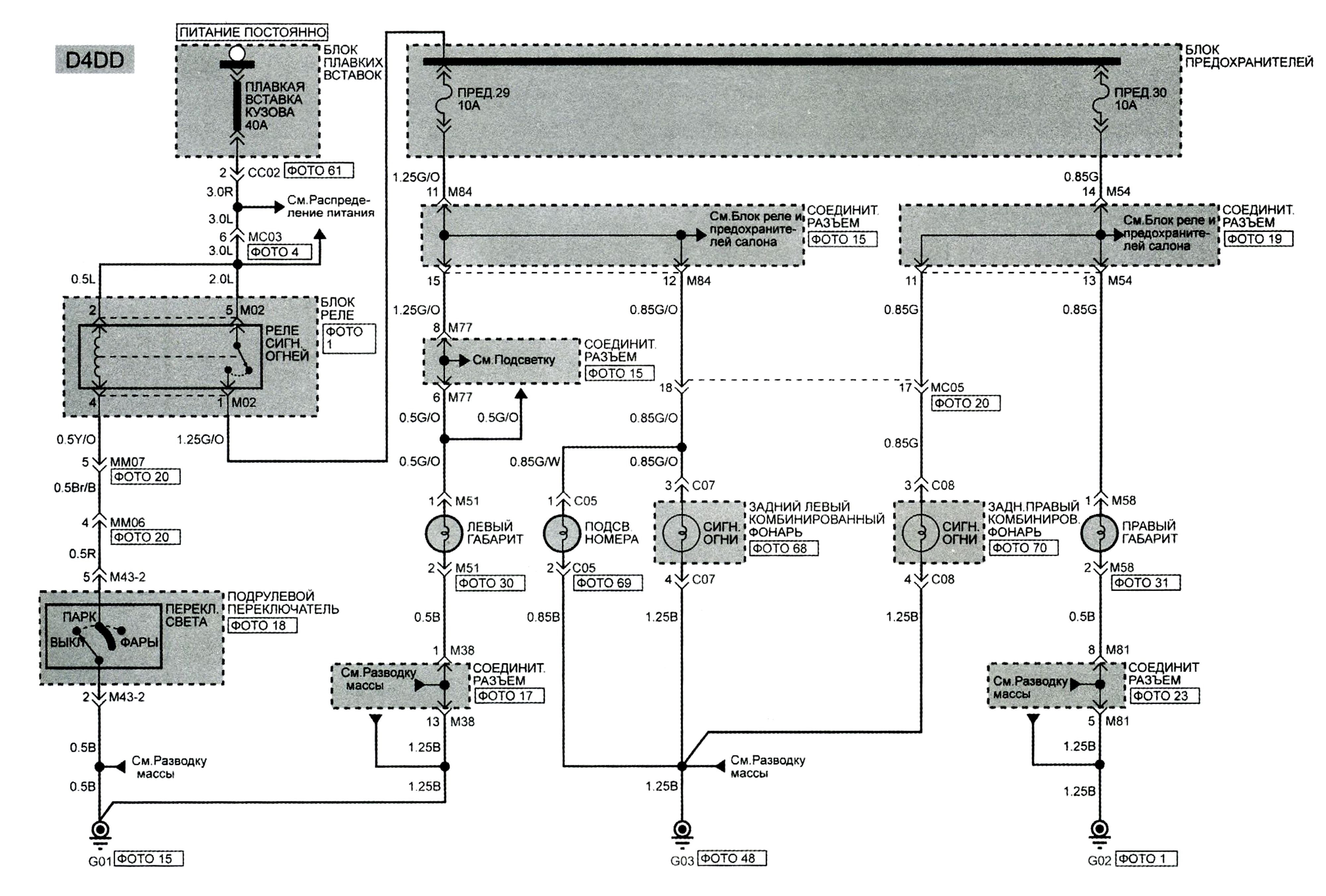
Сигнальные огни.
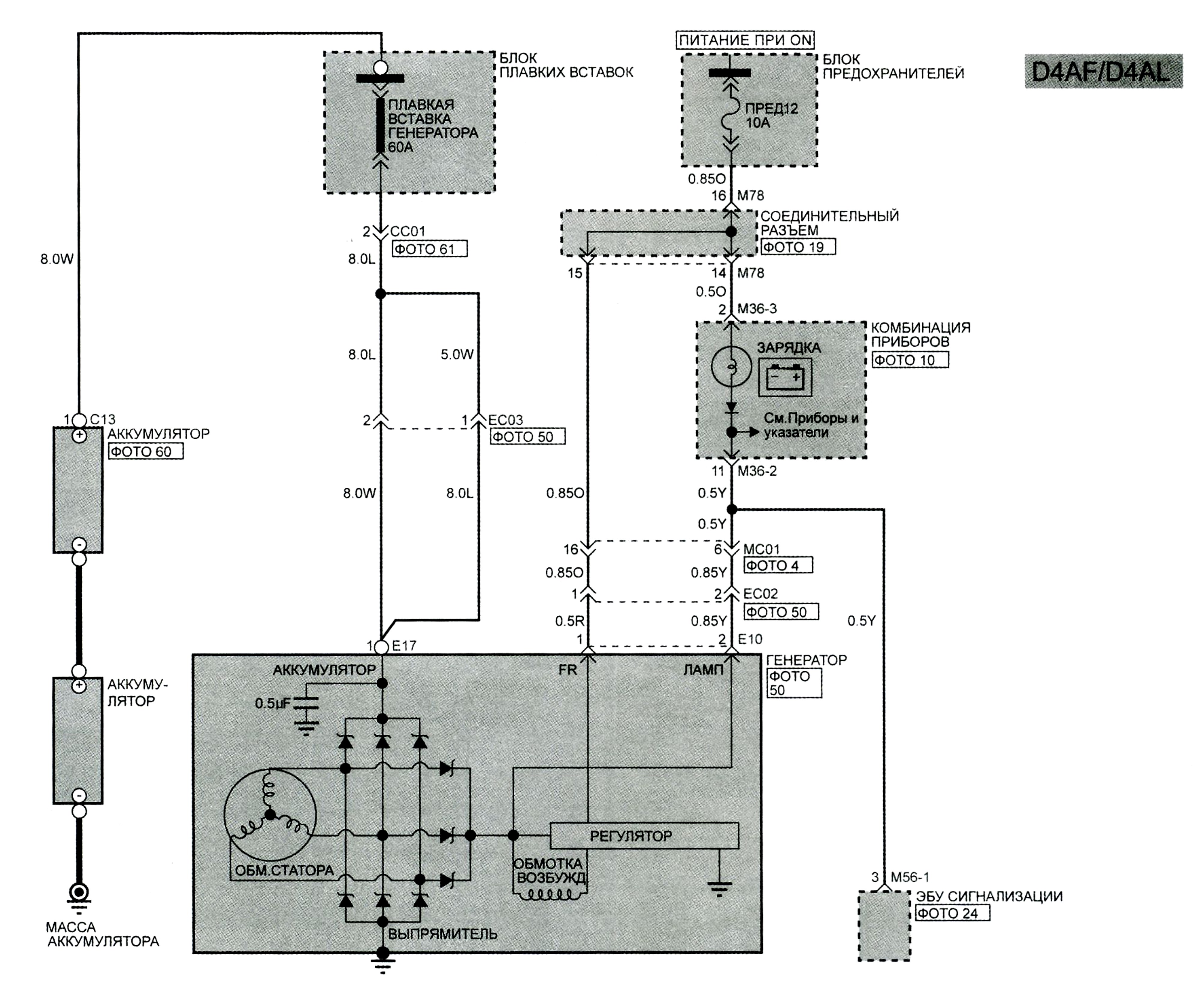
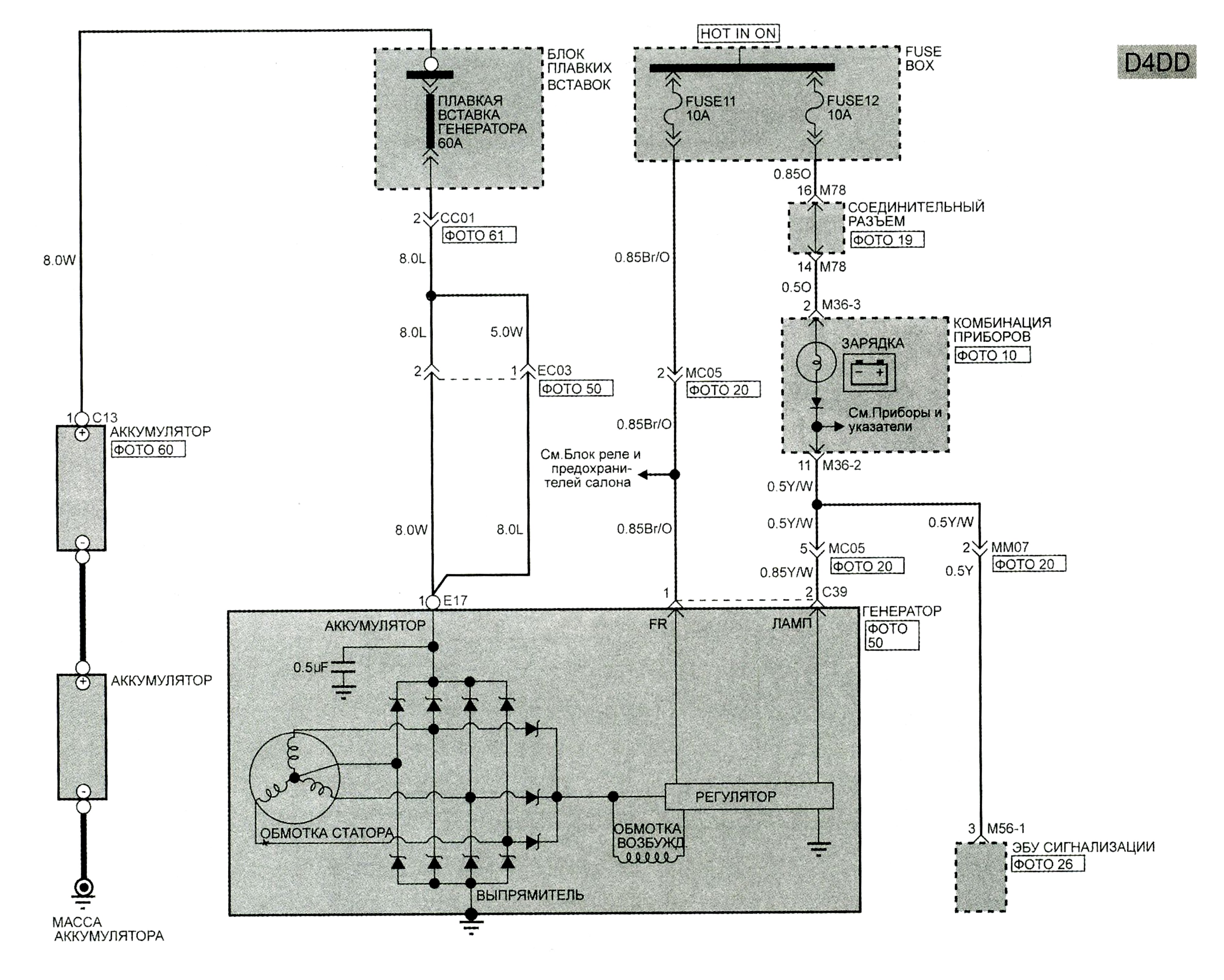
Система зарядки.
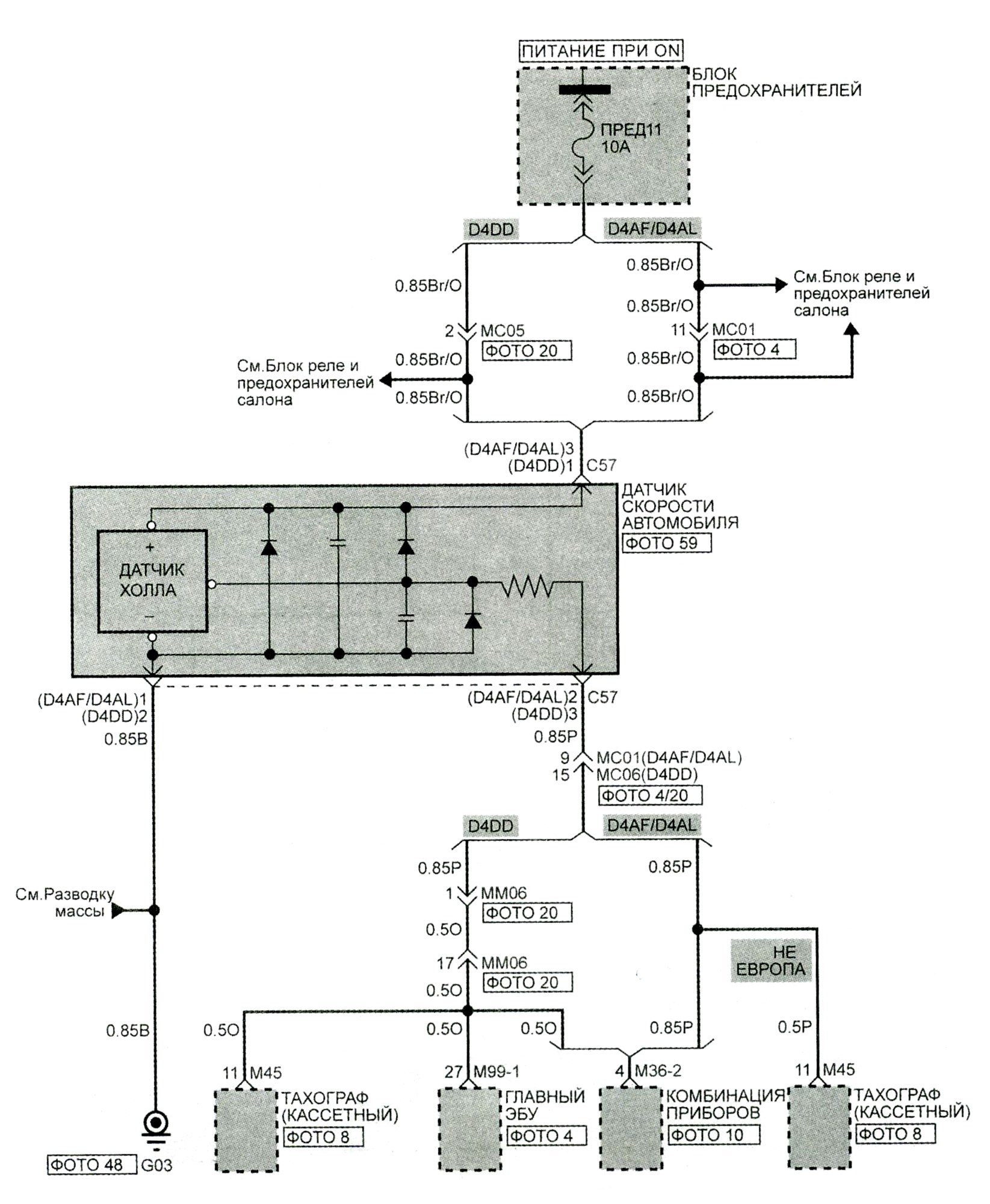
Система определения скорости автомобиля.
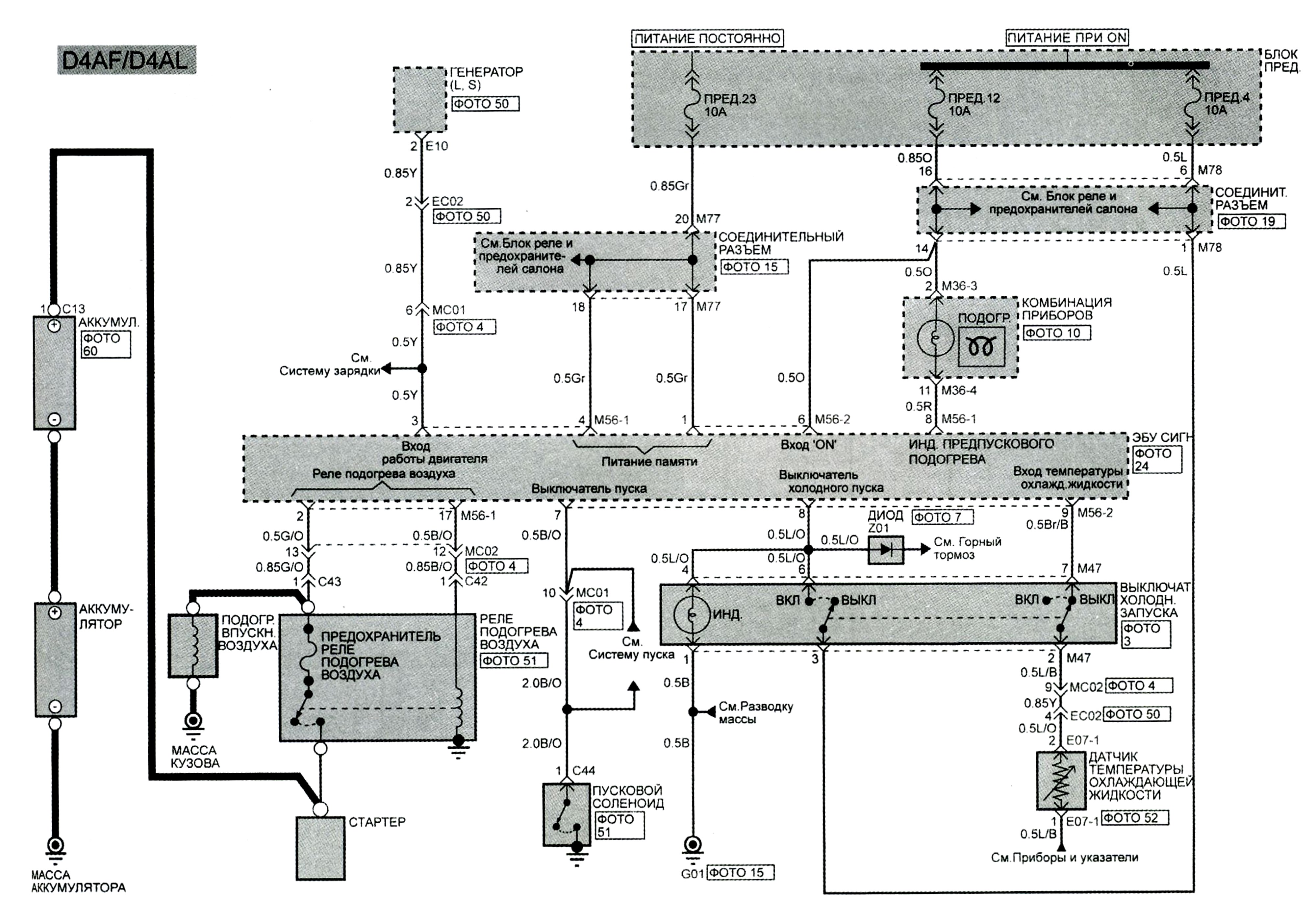
Система предпускового подогрева.
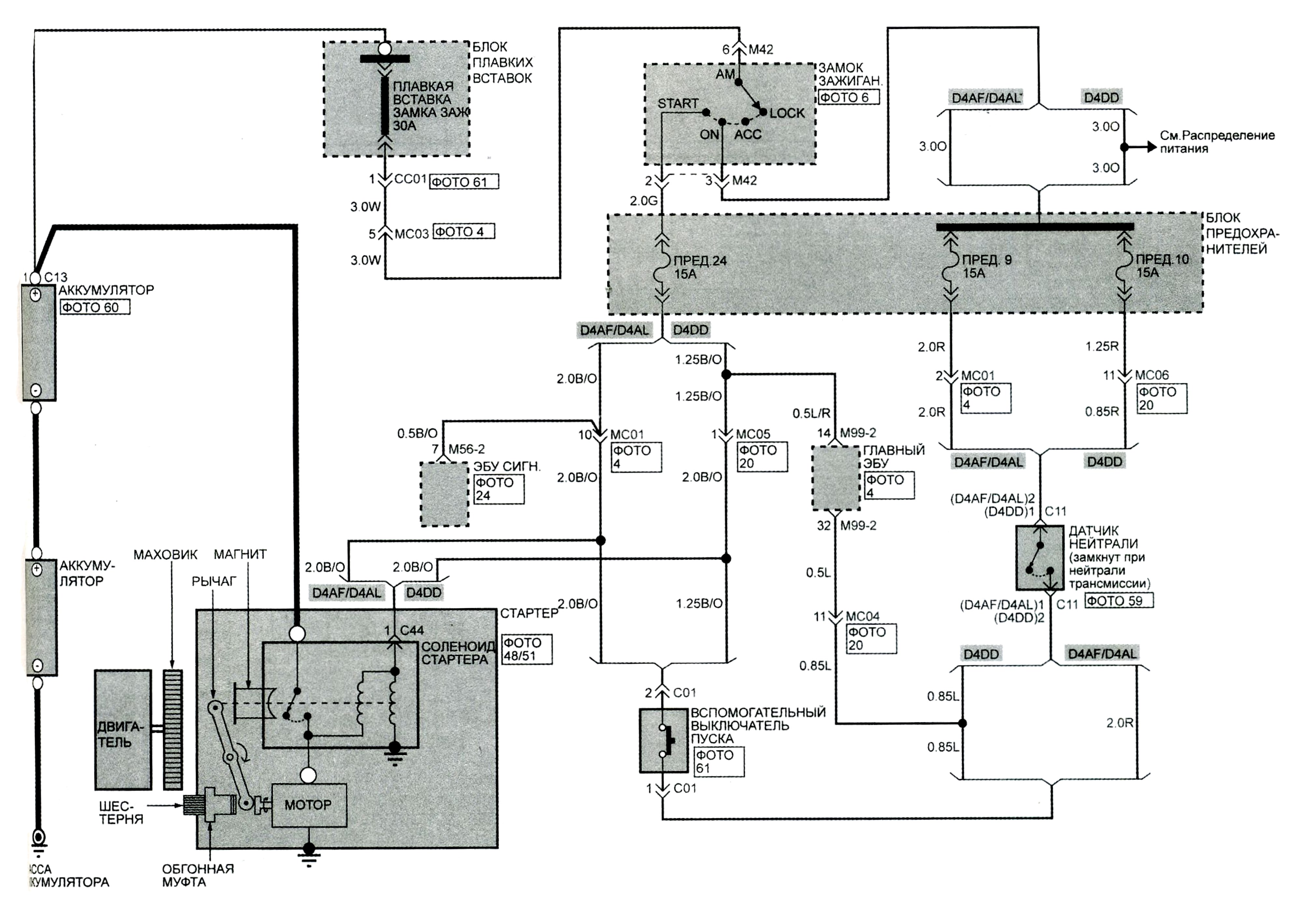
Система пуска.
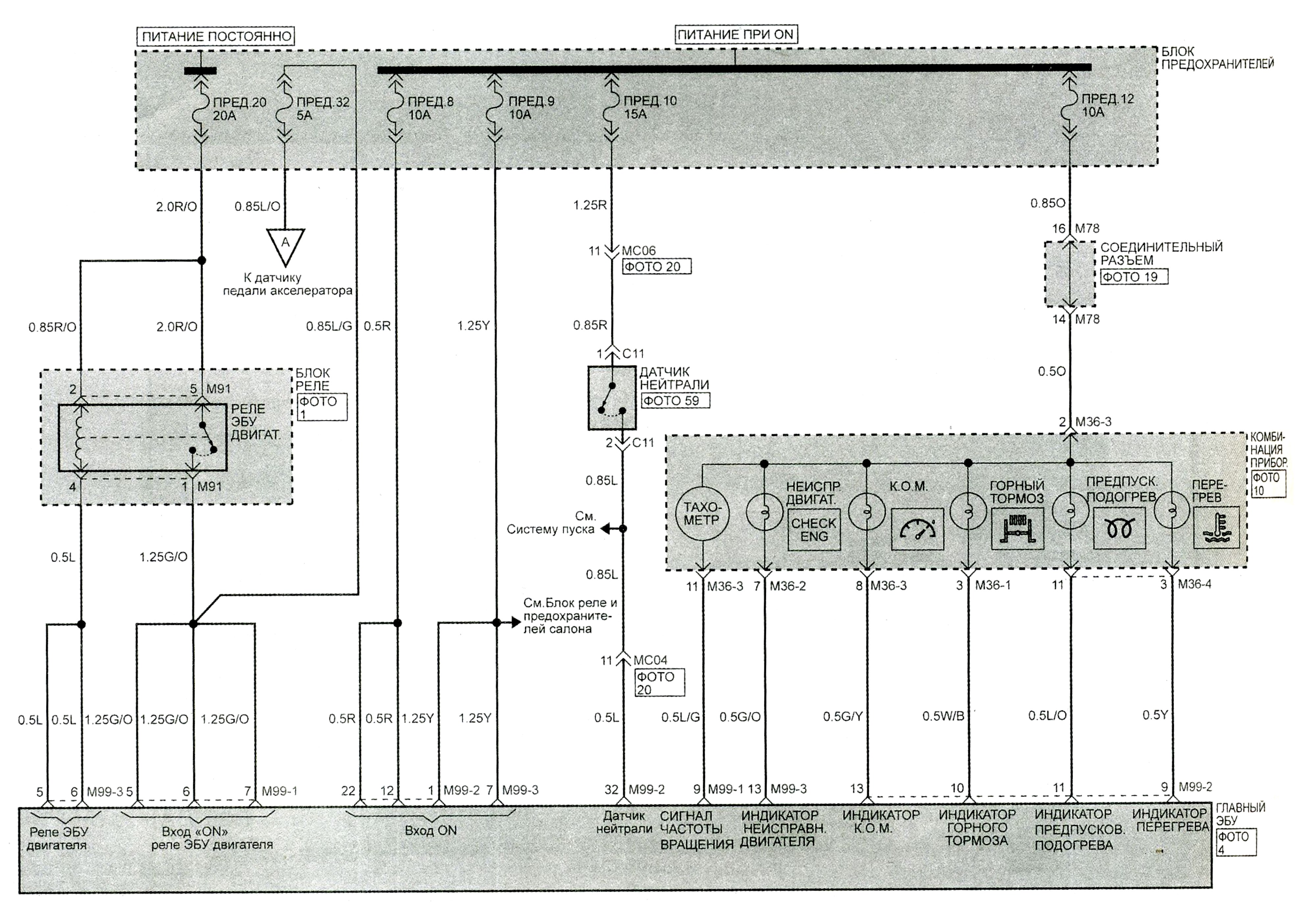
Система управления впрыском.
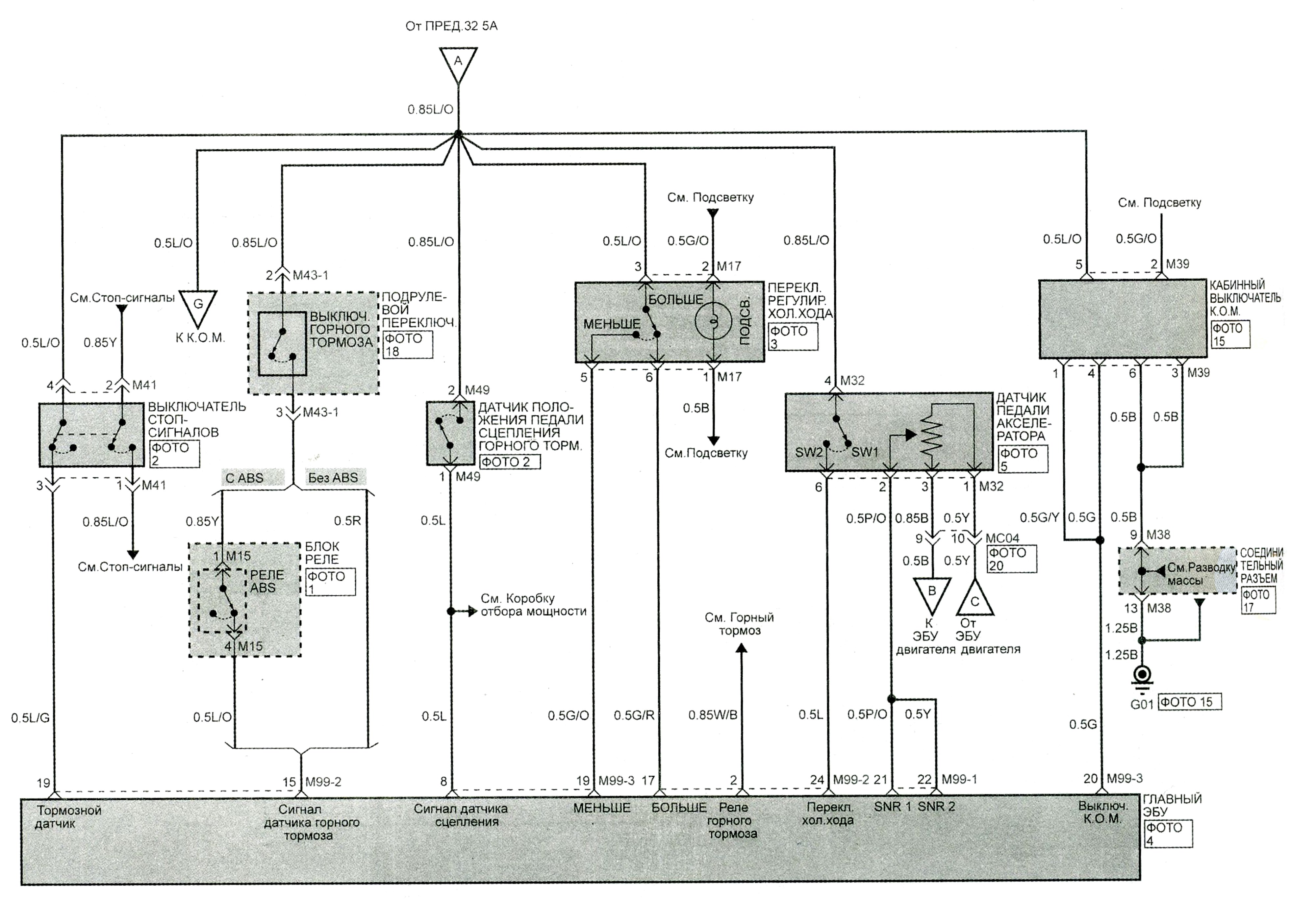
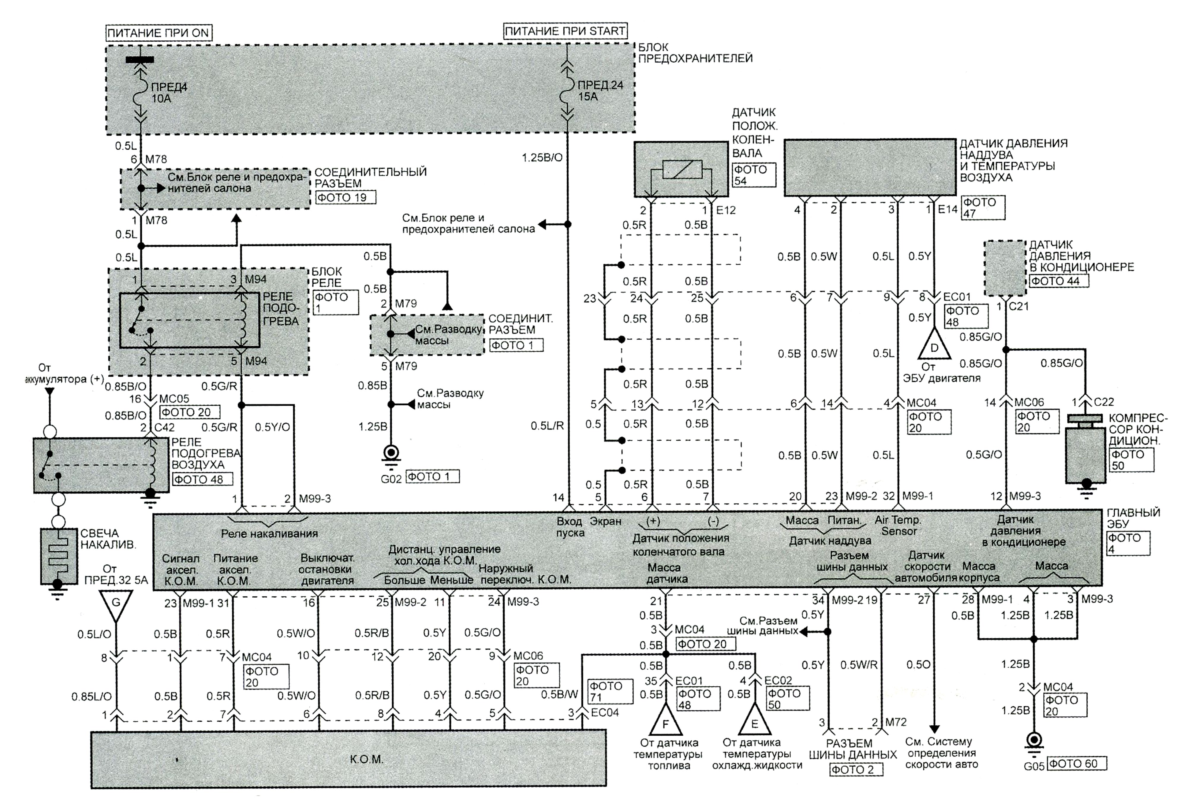
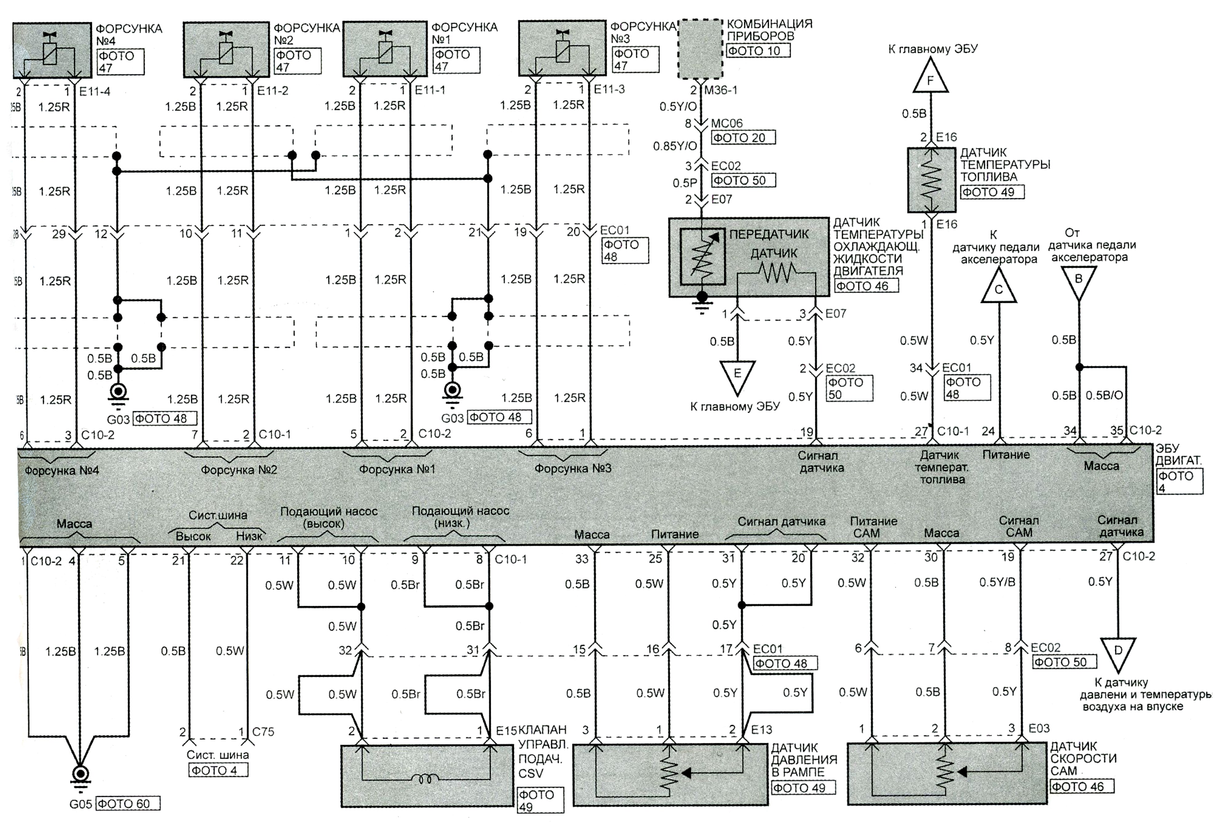
Стеклоочистители и омыватели.
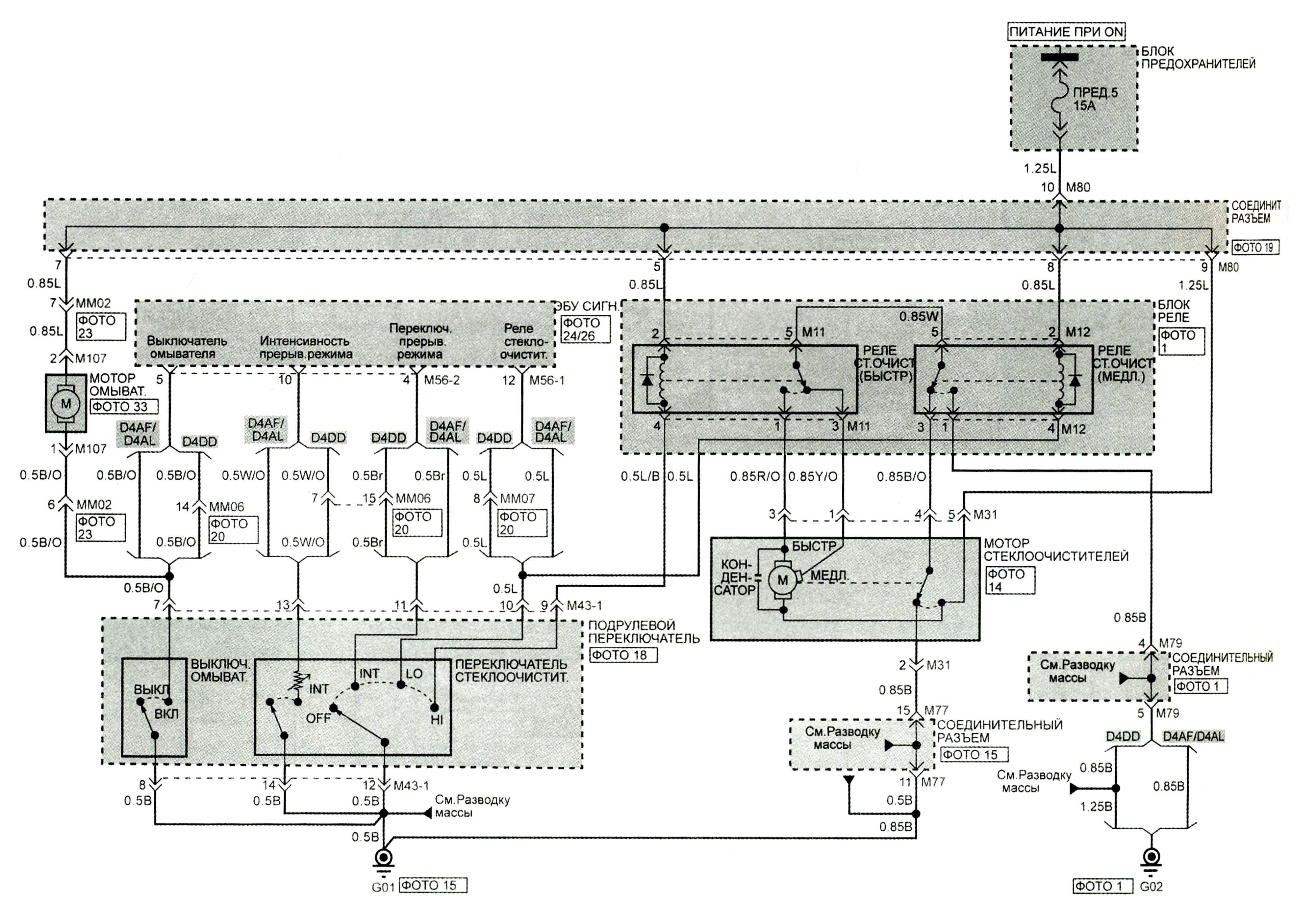
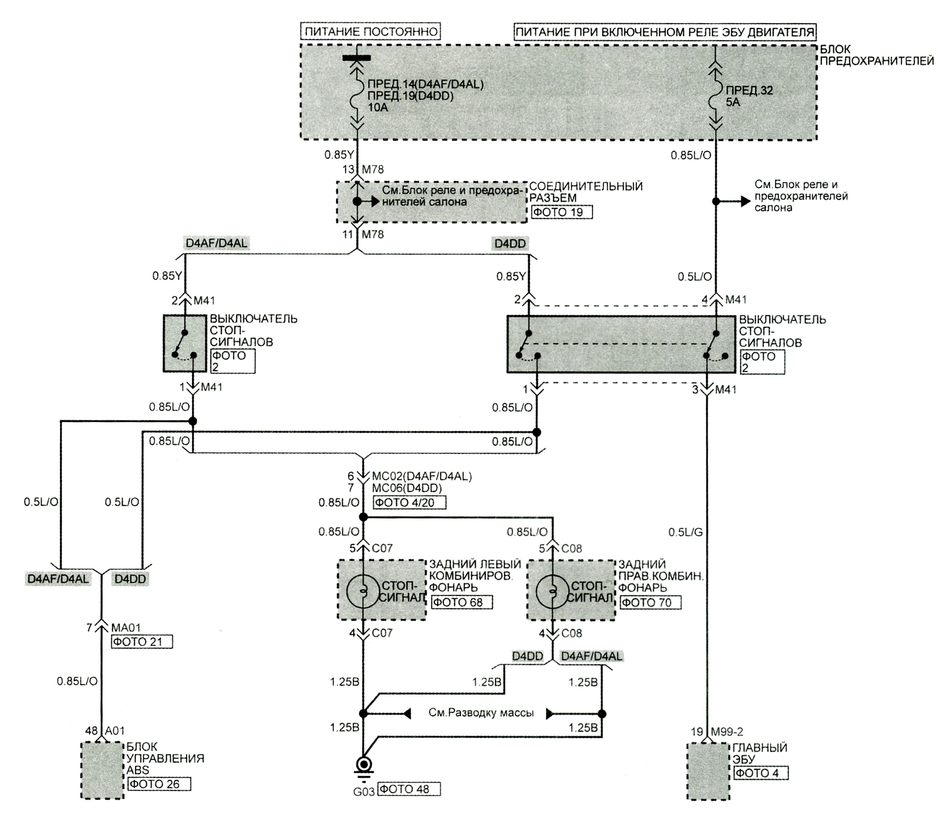
Стоп-сигналы.
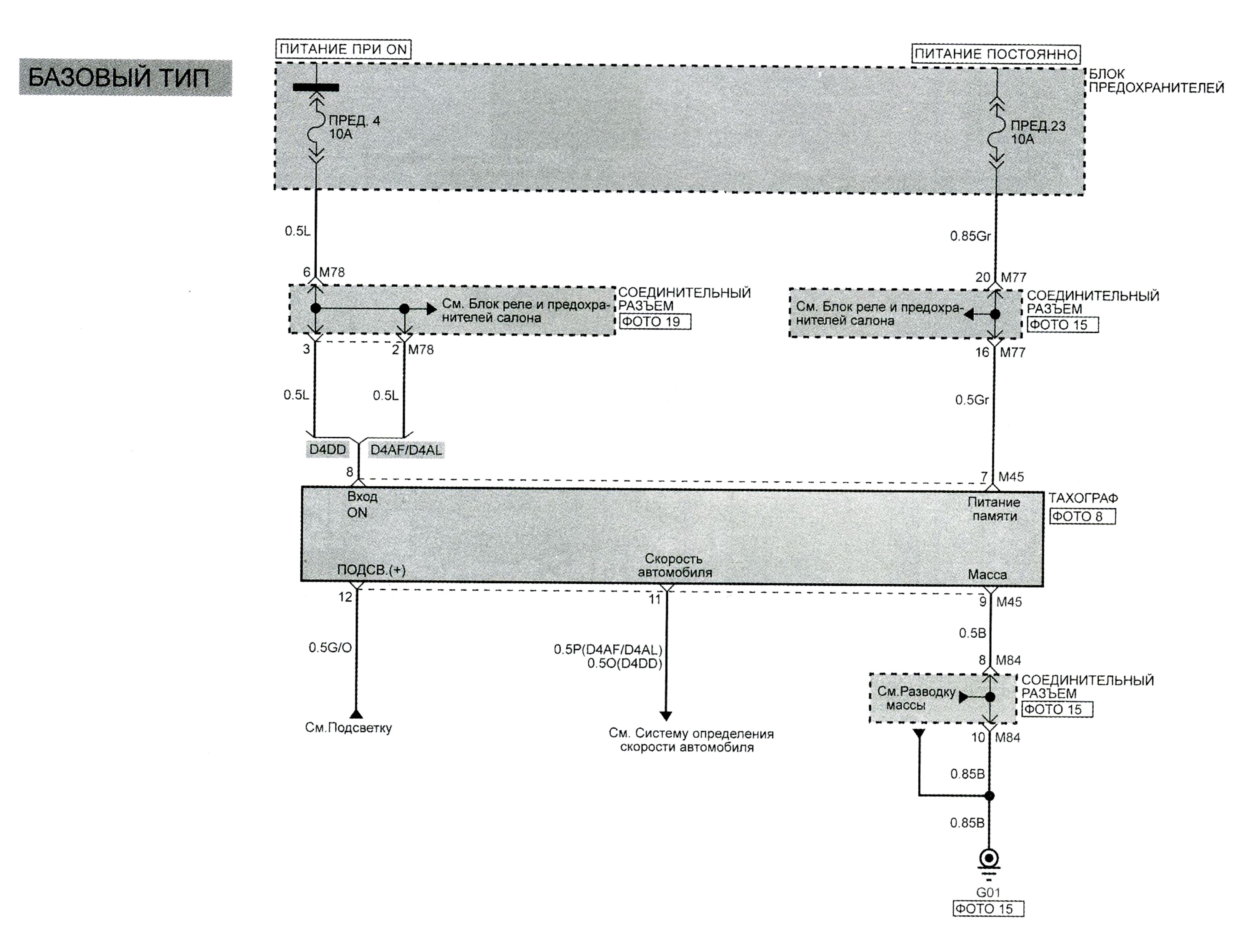
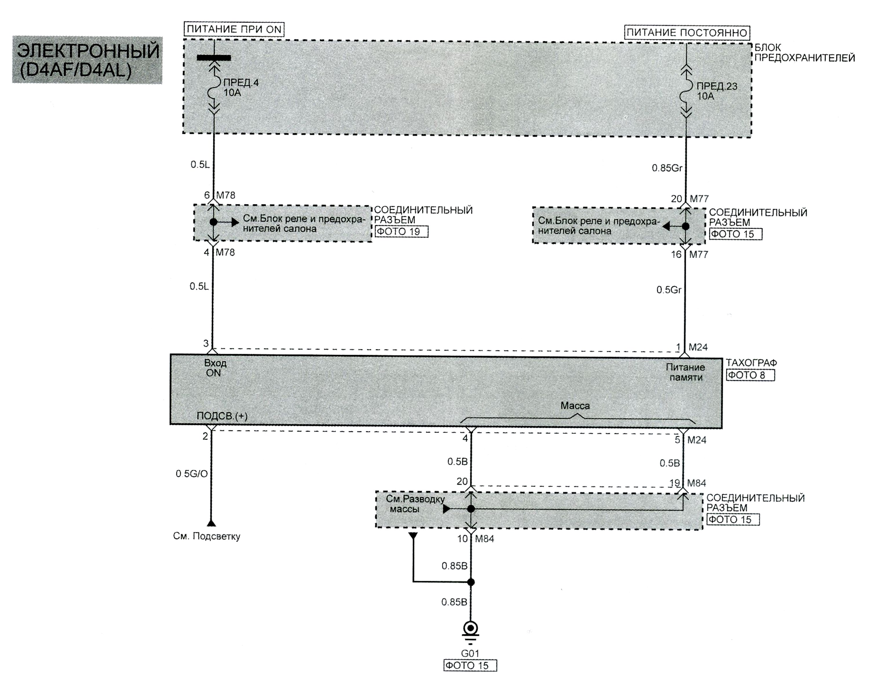
Тахограф.
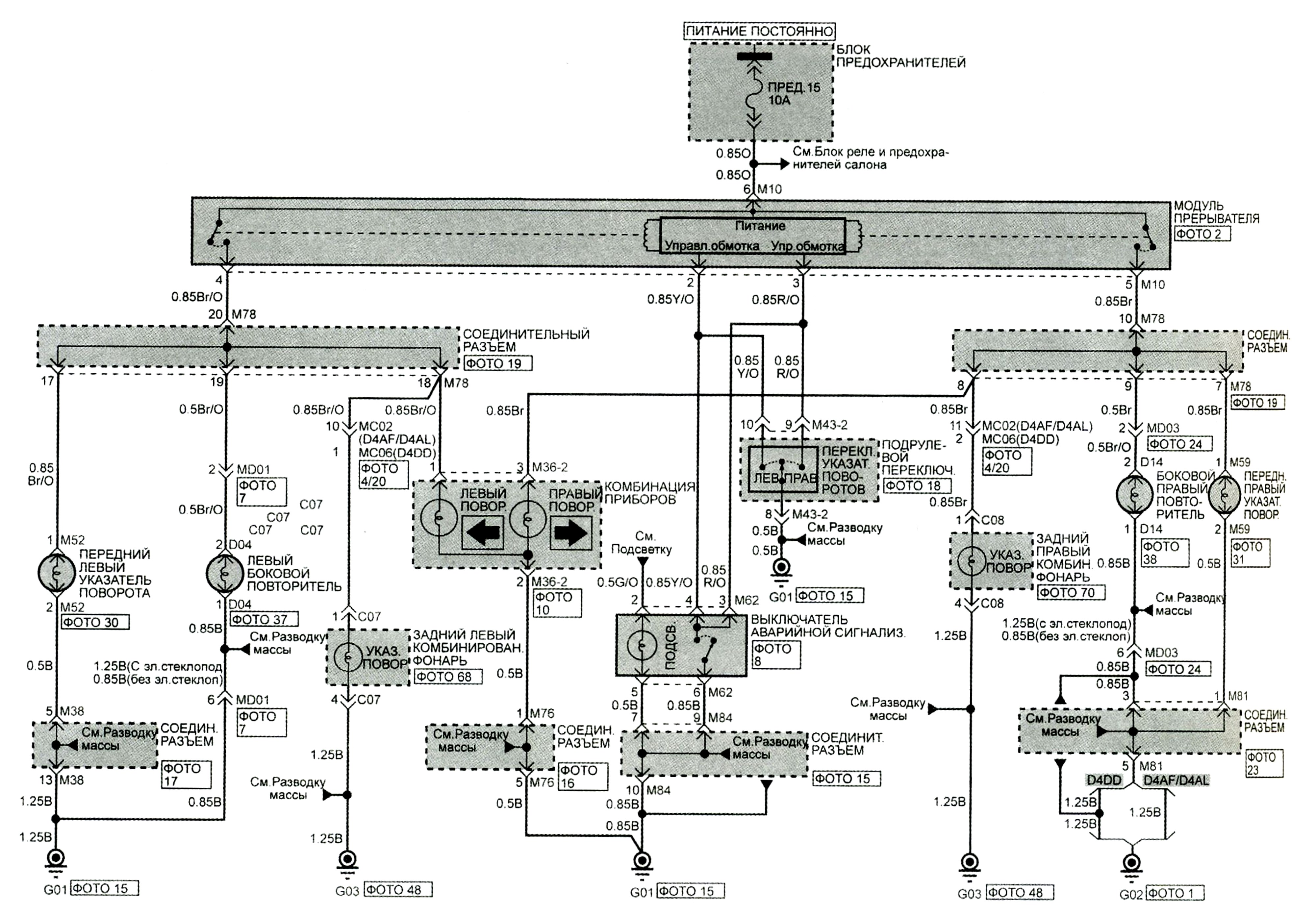
Указатели поворотов и аварийная сигнализация.
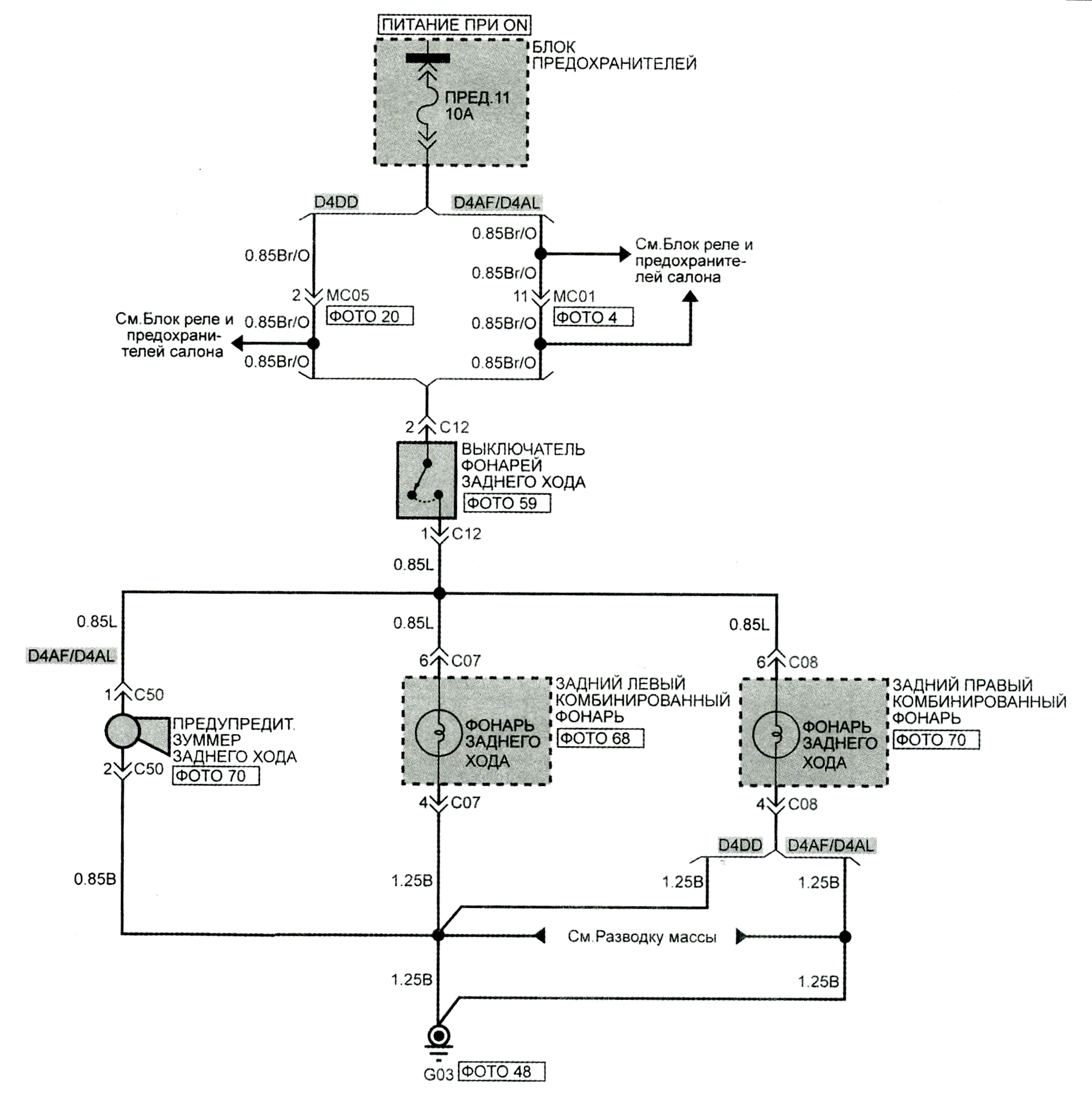
Фонари заднего хода.
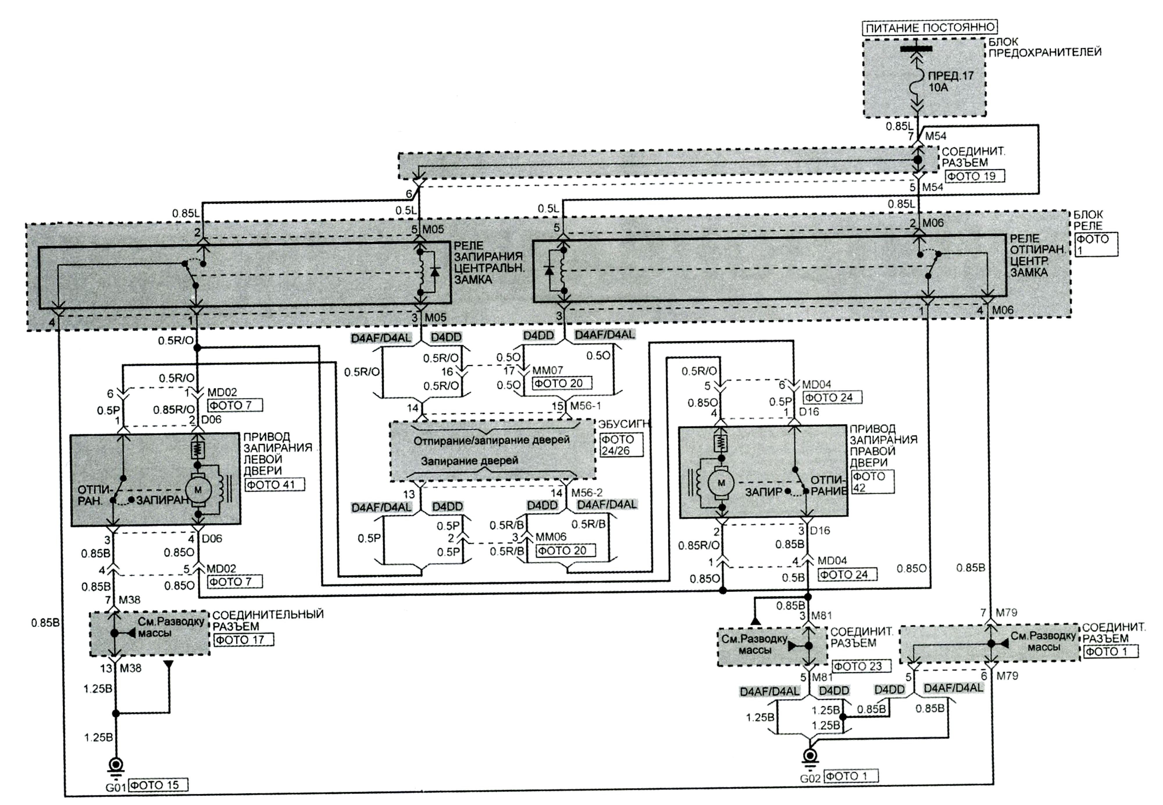
Центральный замок.
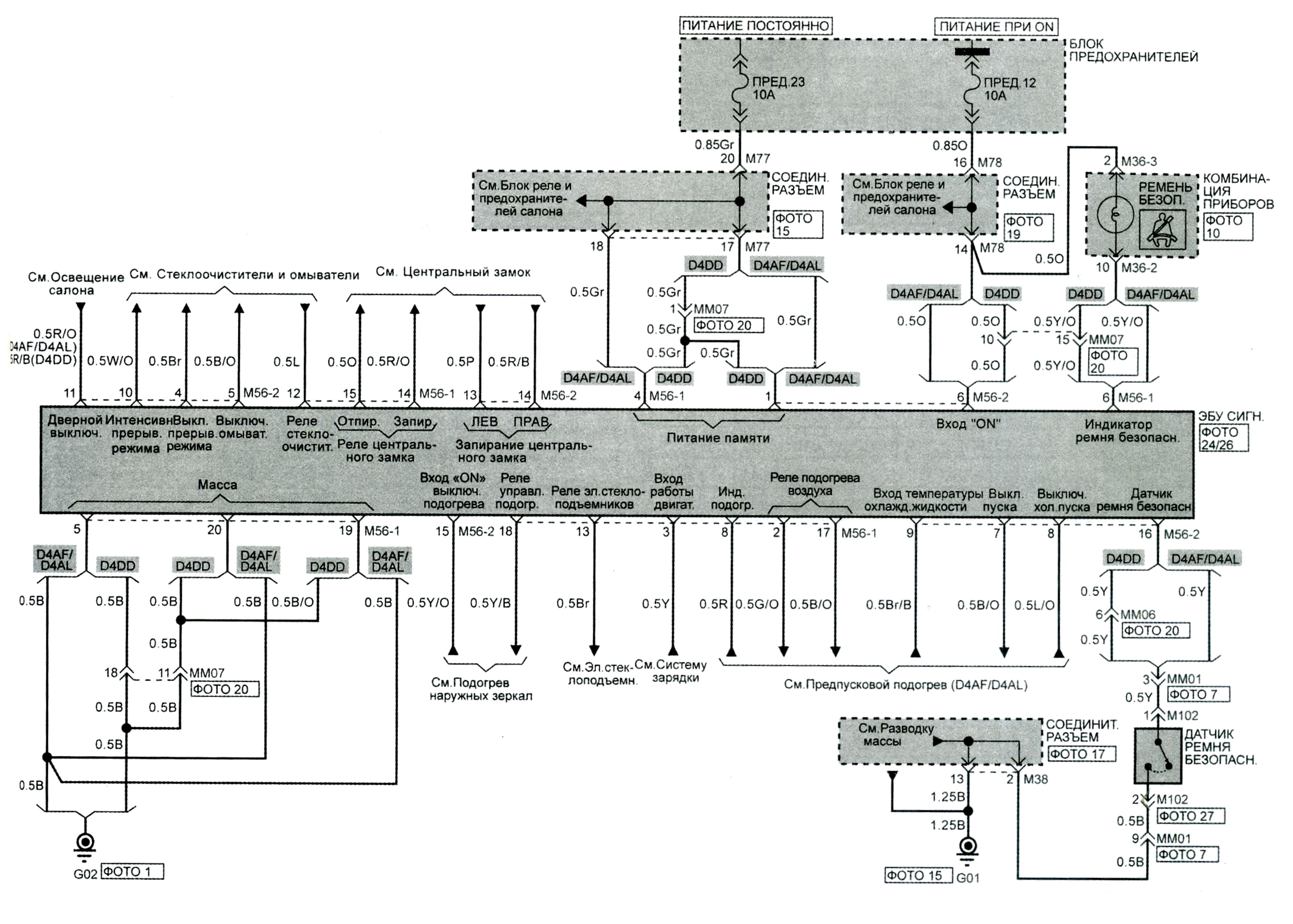
Электронная система управления сигнализацией (ETACS).
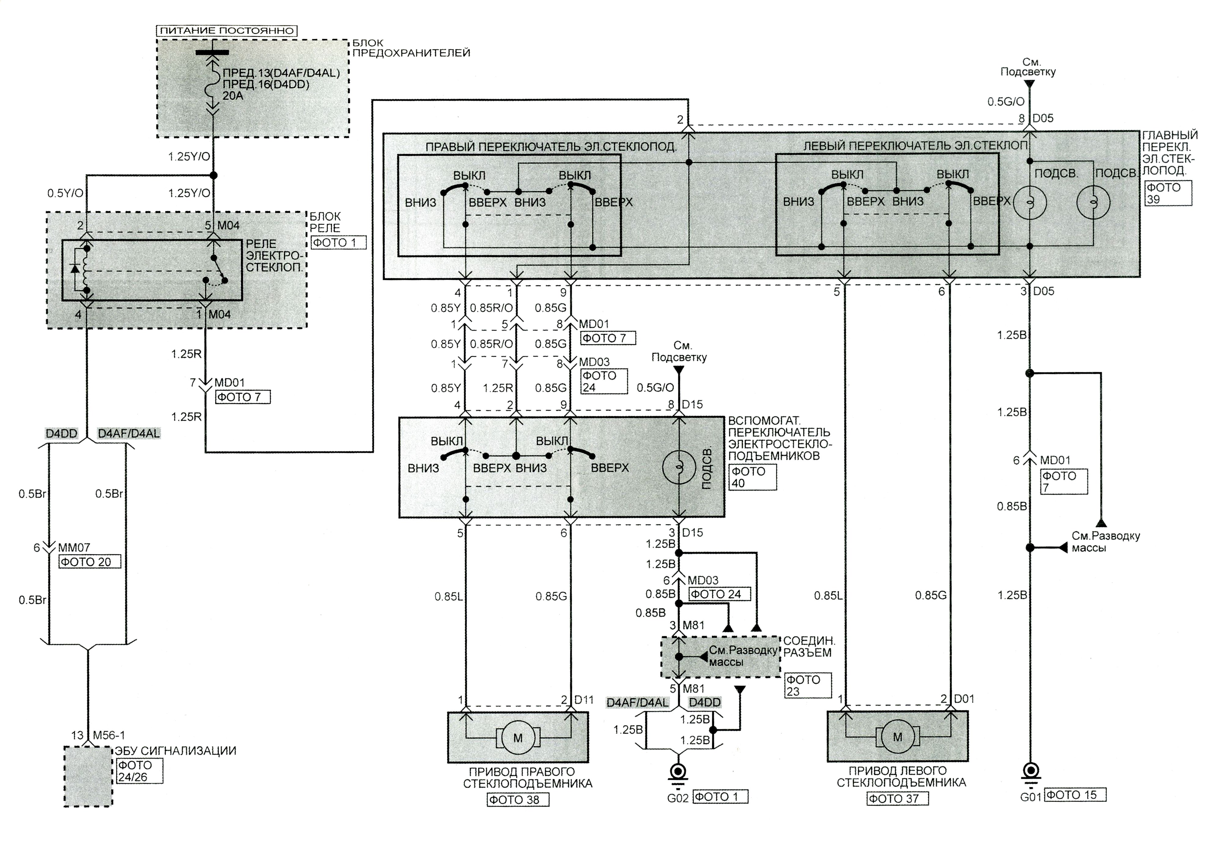
Электростеклоподъёмники.
Поделиться ссылкой:
Похожие статьи
 Предохранители KIA Bongo и Hyundai Porter 2.
 Рулевое управление Hyundai HD 120.
 Электрооборудование Hyundai HD 65/72/78.
 Схема электрооборудования двигателя Hyundai Porter.
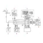 Схема стеклоочистителей Hyundai Porter.
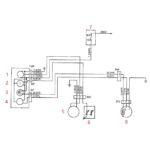 Схема подключения датчиков и указателей уровня топлива, температуры охлаждающей жидкости и тахометра Hyundai Porter.
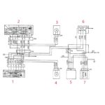 Схема подключения электрических стеклоподъемников Hyundai Porter.
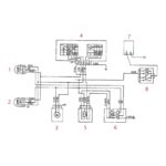 Схема подключения ближнего-дальнего света фар Hyundai Porter.
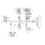 Схема подключения указателей поворота Hyundai Porter.
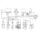 Схема подключения стартера Hyundai Porter.
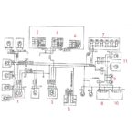 Схема подключения габаритных огней и ламп подсветки Hyundai Porter.
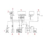 Схема подключения свечей предпускового подогрева Hyundai Porter.
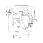 Схема подключения блока управления ETACS Hyundai Porter.
 Предохранители и реле Kia Bongo III, Hyundai Porter II.
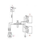 Схема подключения стоп сигнала Hyundai Porter.
