Схемы электрооборудования Chery Tiggo (J11, Ruihu, T11) (English).
Схемы электрооборудования автомобилей Chery Tiggo (J11, Ruihu, T11) (English).
Diagram Description.
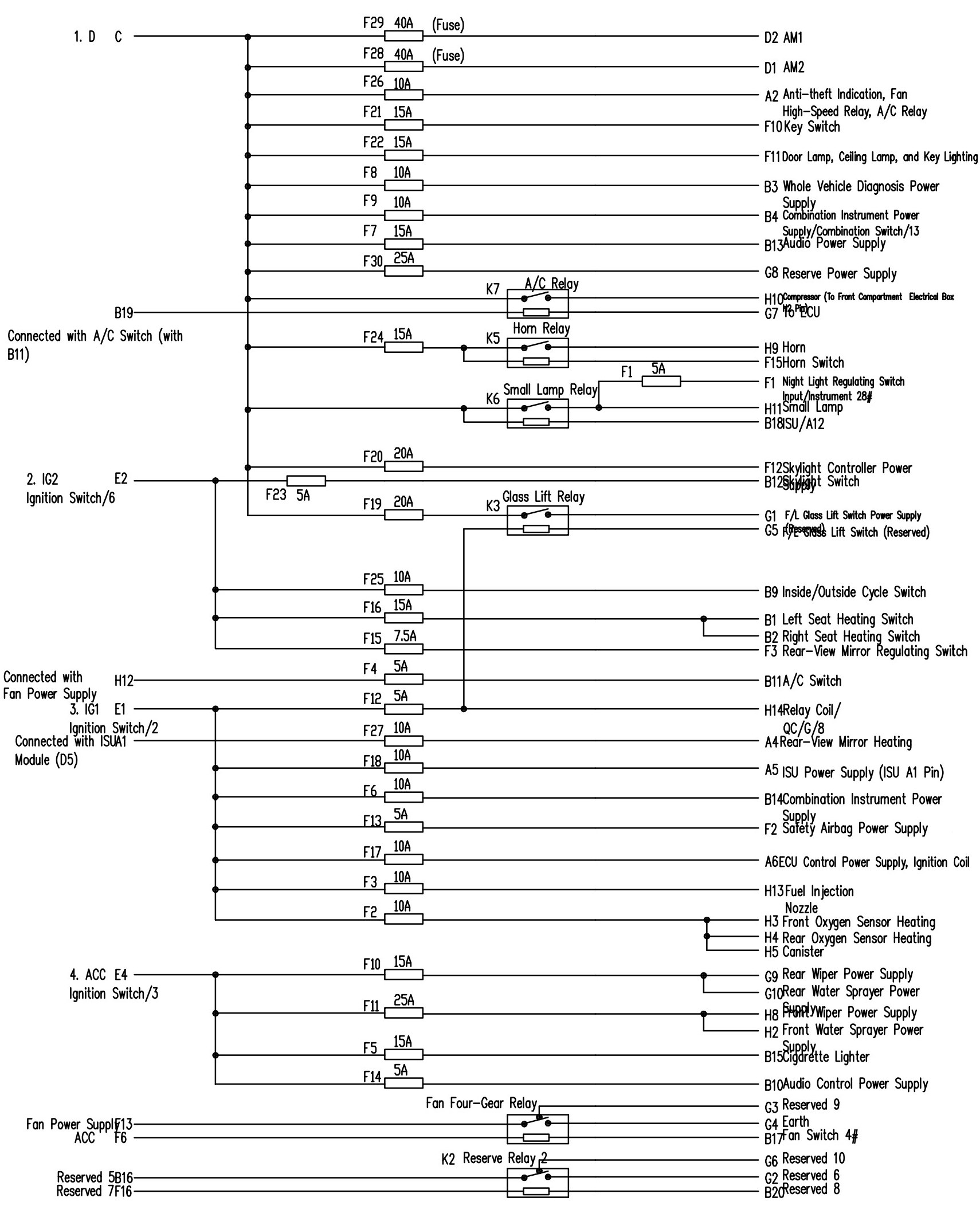
1. Circuit Number for Relay Box
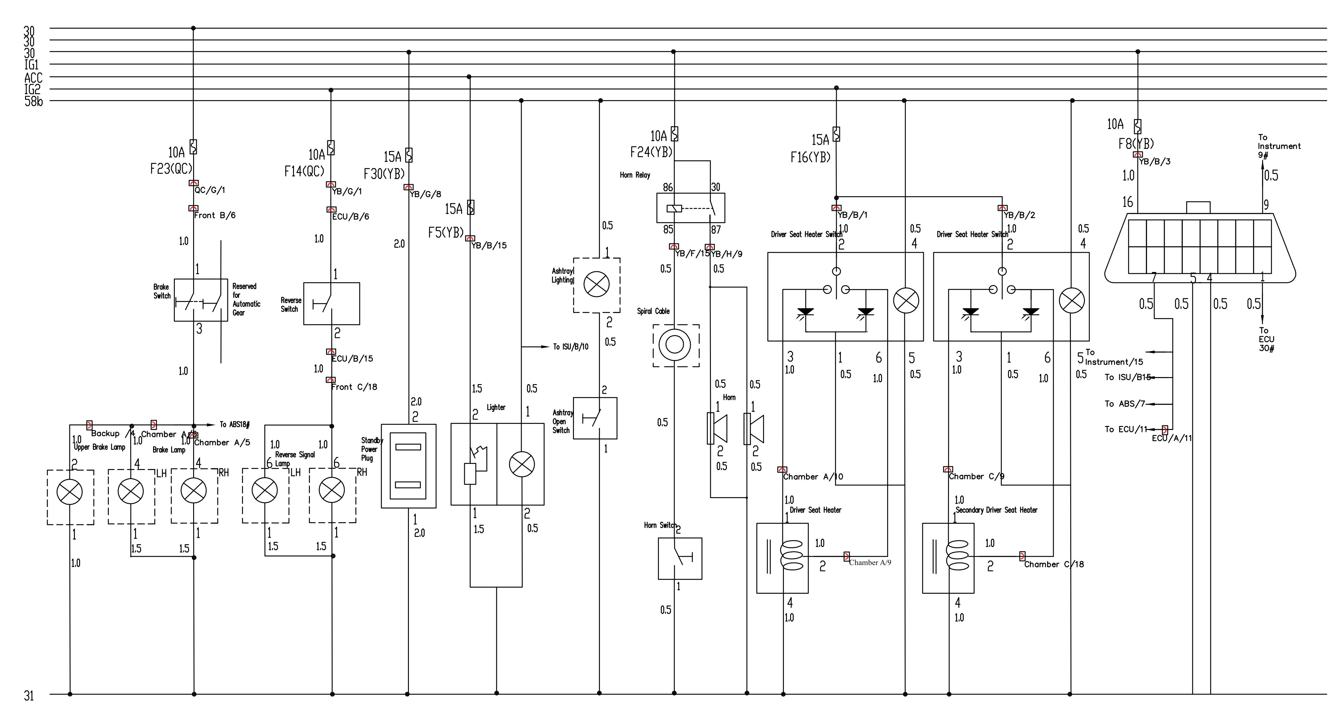
30: means the circuit is directly from the battery;
IG1: means the 1st gear of ignition switch;
IG2: means the 2nd gear of ignition switch;
ACC: means the RADIO gear of ignition switch;
31: means the earth wire.
2. Connecting pieces description
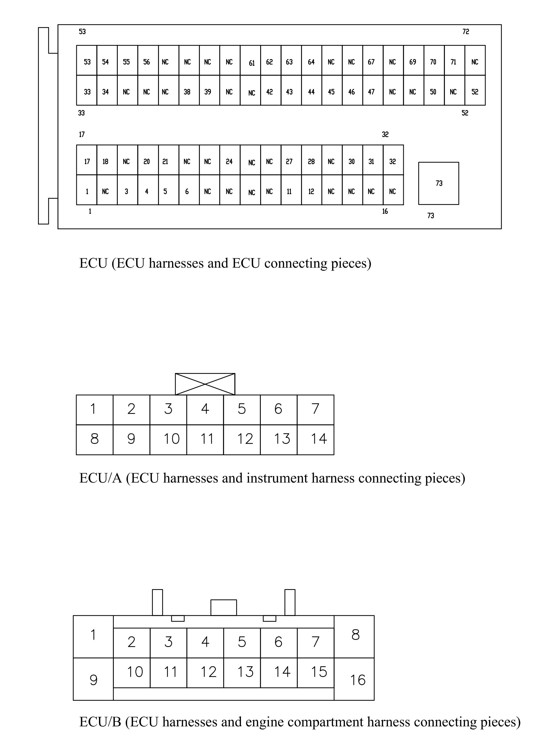
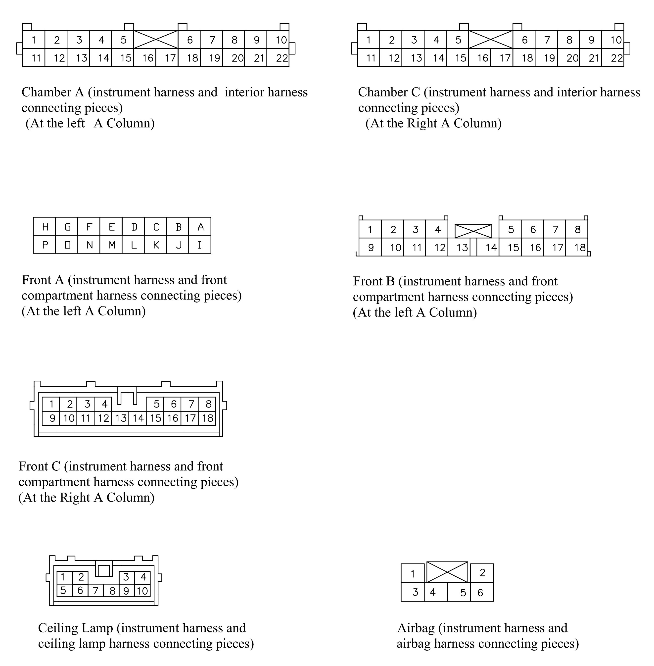
For example: The front A/l means the Terminal 1 (at the instrument wire harness), Connector A of the instrument wire harness and engine compartment wire harness.
ECU/A/l means the Terminal 1 (at the ECU wire harness), Connector A of the ECU wire harness and instrument wire harness.
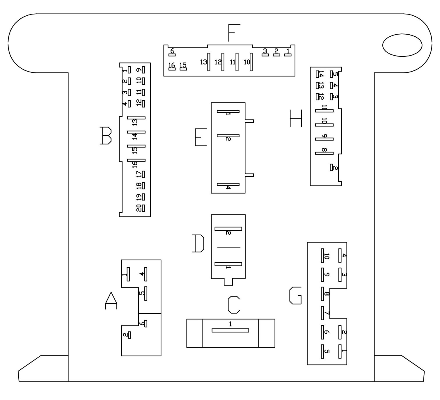
QB/A/1 means the Terminal 1, Connector A of the instrument electrical box.
QC/A/1 means the Terminal 1, Connector A of the front compartment electrical box.
Fl (YB) means the Fuse 1 of the instrument electrical box.
Fl (QC) means the Fuse 1 of the engine compartment electrical box.
3. ISU connecting pieces & terminals description
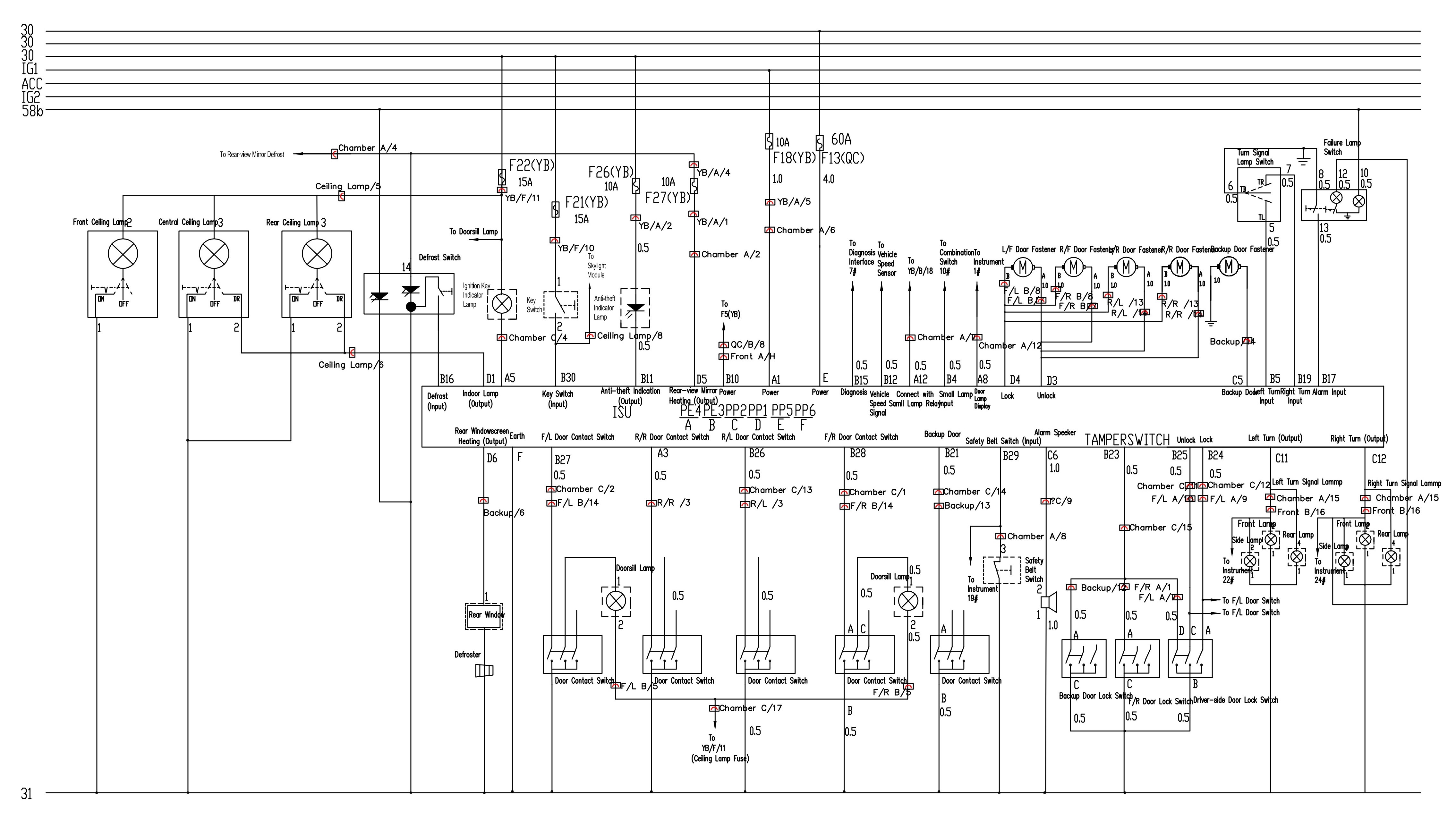
ISU PE4 means the port A, PE3 means the port В, PE2 means the port С, PEI means the port D, PE5 means the port E, and PE6 means the port F.
4. The main reference model related to this circuit diagram is the 2.4 model with basic configuration. It is hard to avoid the occurrence of errors due to the limit of time. If you find some unconformities to the actual conditions in the course of use, please contact us, service department of chery international.
ECU Harness Connecting Piece.
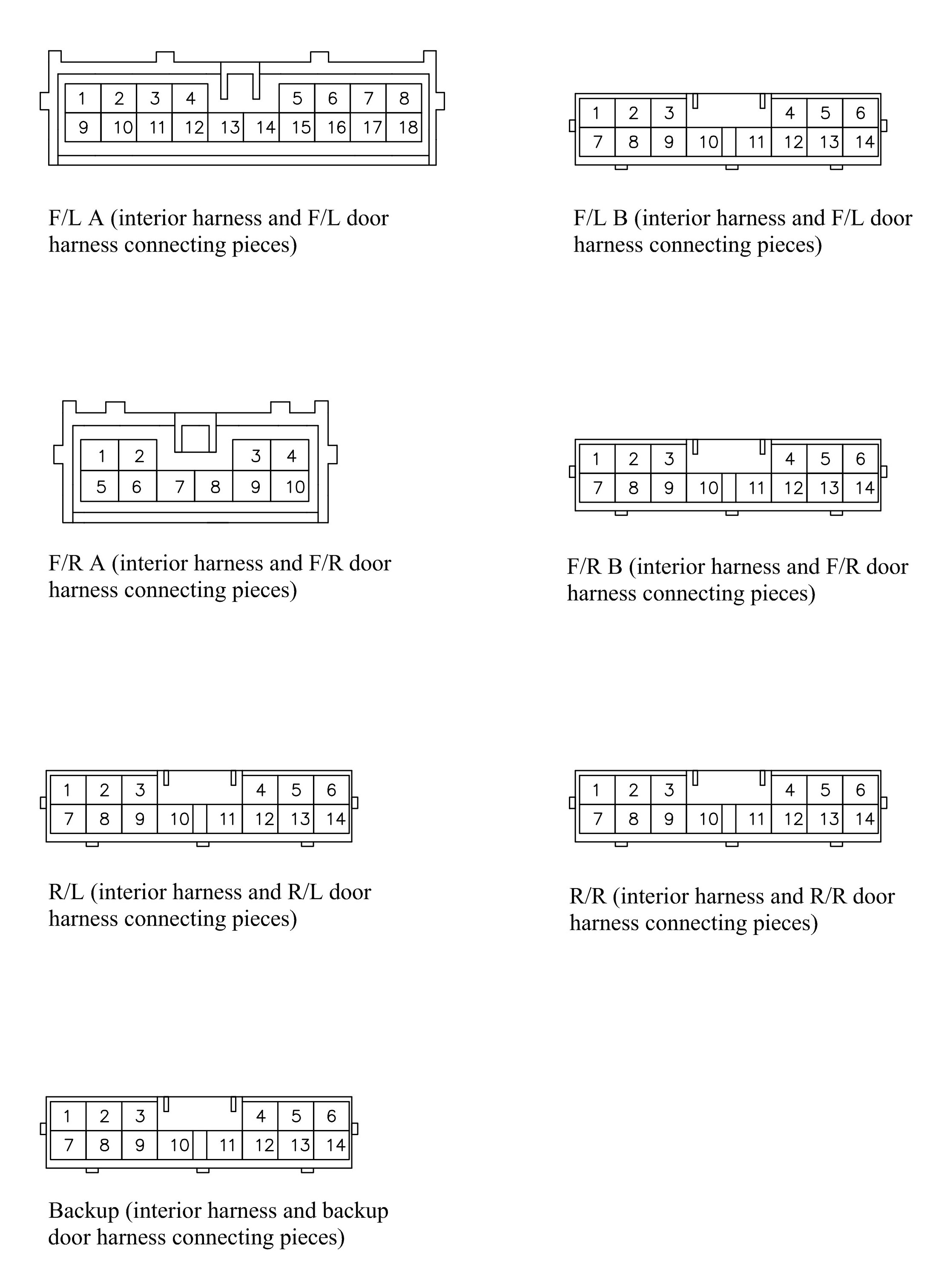
Four Doors and Backup Door Connecting Pieces.
Instrument Harness Connecting Pieces. Interior Harness and Front Compartment Harness Connecting Pieces.
Startup and Charging System.
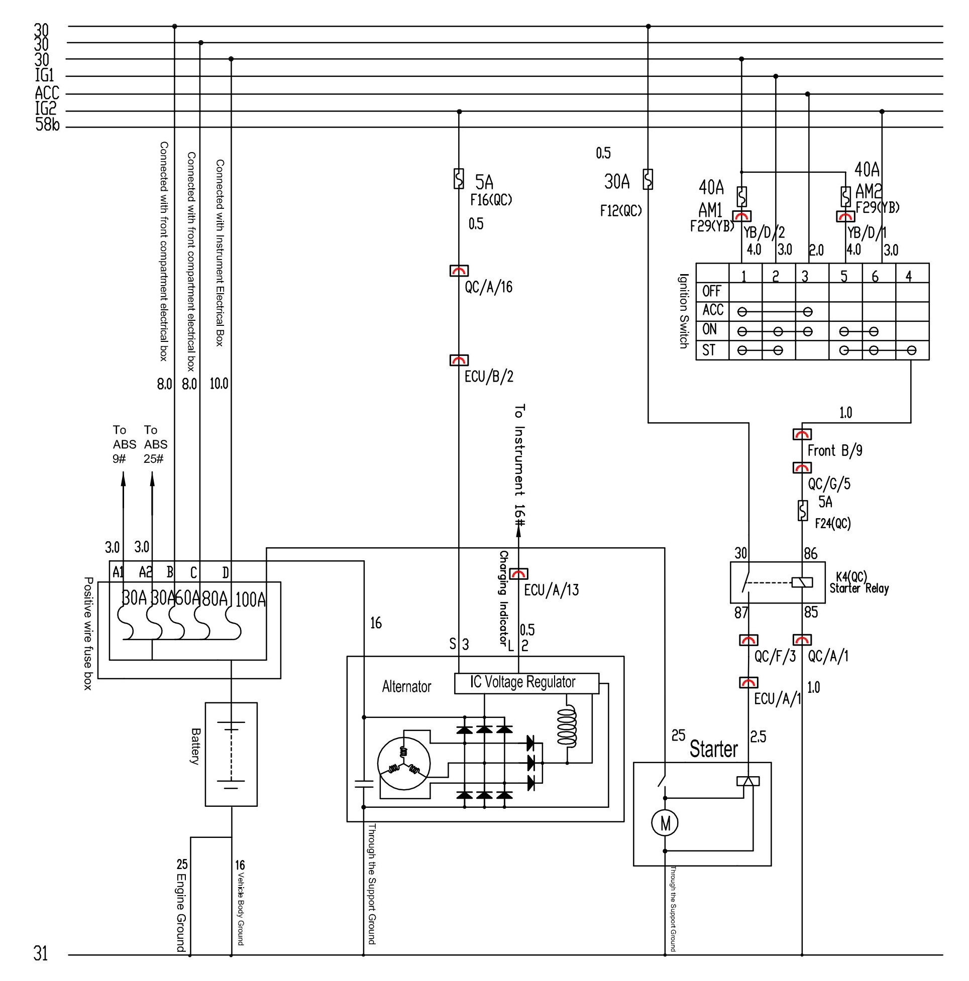
1. The pins 1 and 5 of ignition switch are available for the power supply of battery 30.
2. The pin 2 of ignition switch is applied for the IG1 power supply. This pin is divided into two branches, one of which connects to the instrument electrical box El; and the other connects to the front compartment electrical box G3 using the connector (front B/10).
3. The pin 2 of ignition switch is used for the ACC power supply. This pin is divided into two branches, one of which connects to the instrument electrical box E4; and the other connects to the front compartment electrical box G6 using the connector (front B/18).
4. The pin 2 of ignition switch is designed for the 1G2 power supply. This pin is divided into two branches, one of which connects to the instrument electrical box E2; and the other connects to the front compartment electrical box 16 using the connector (front A/L).
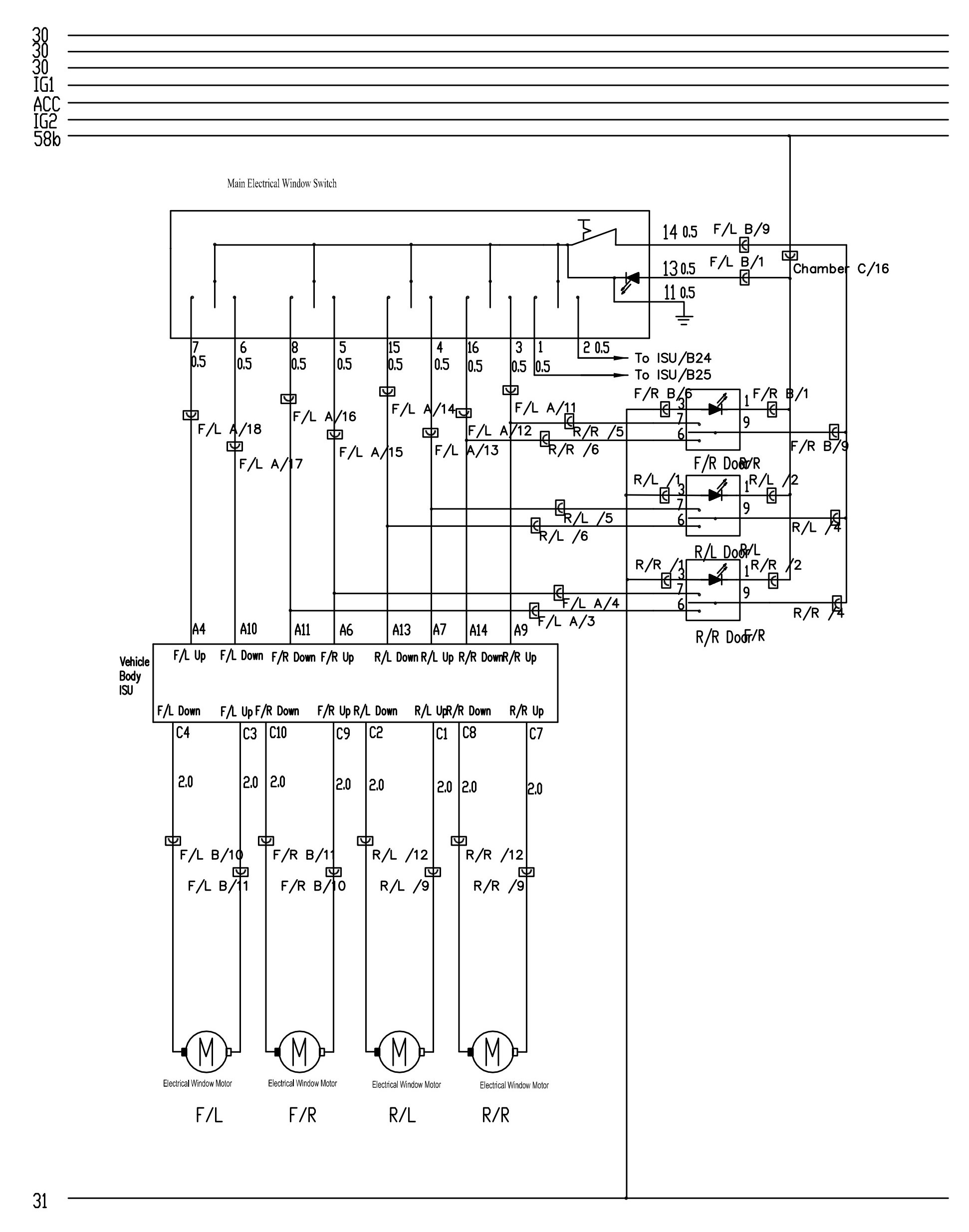
Glass Lift System.
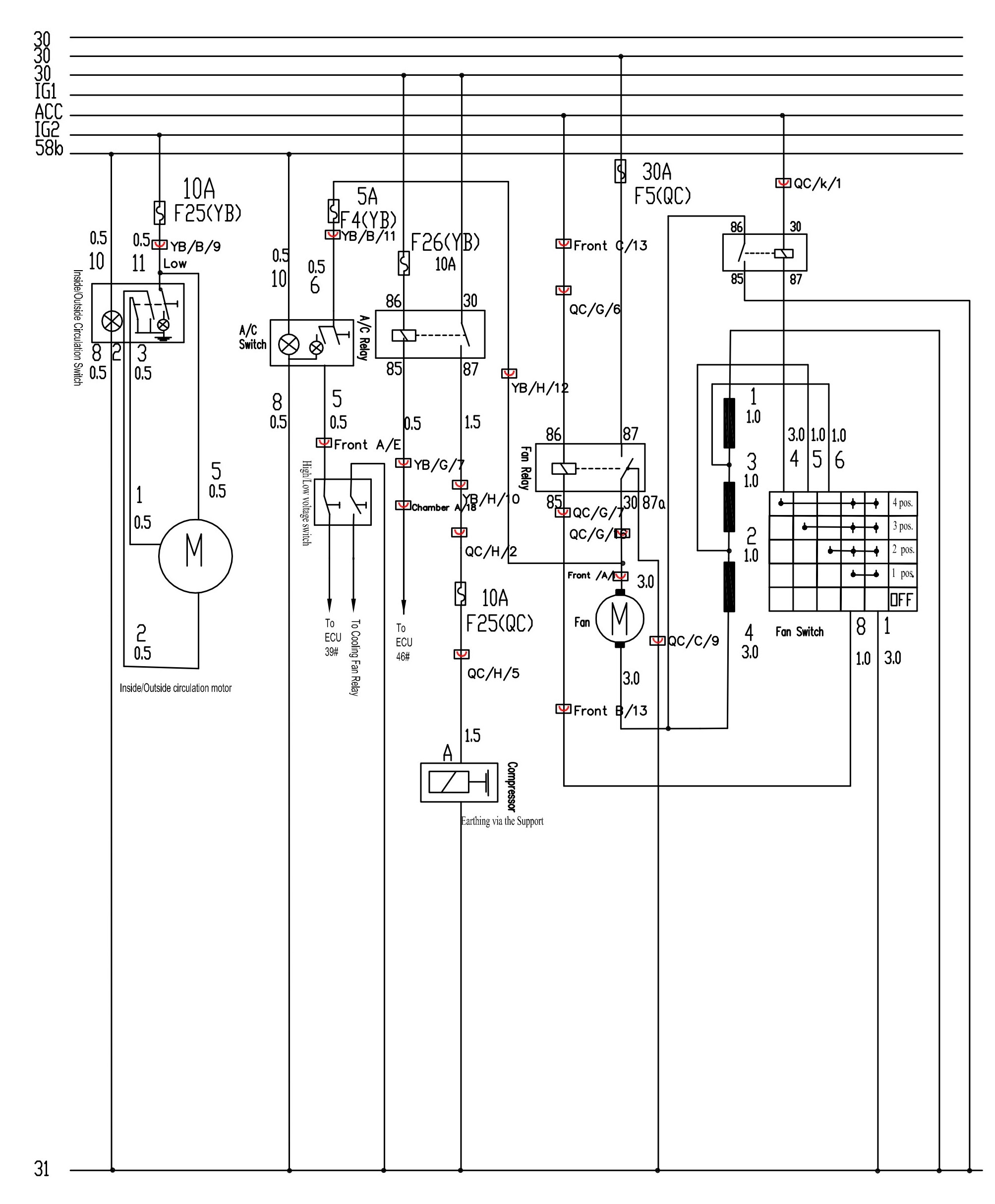
A/C System.
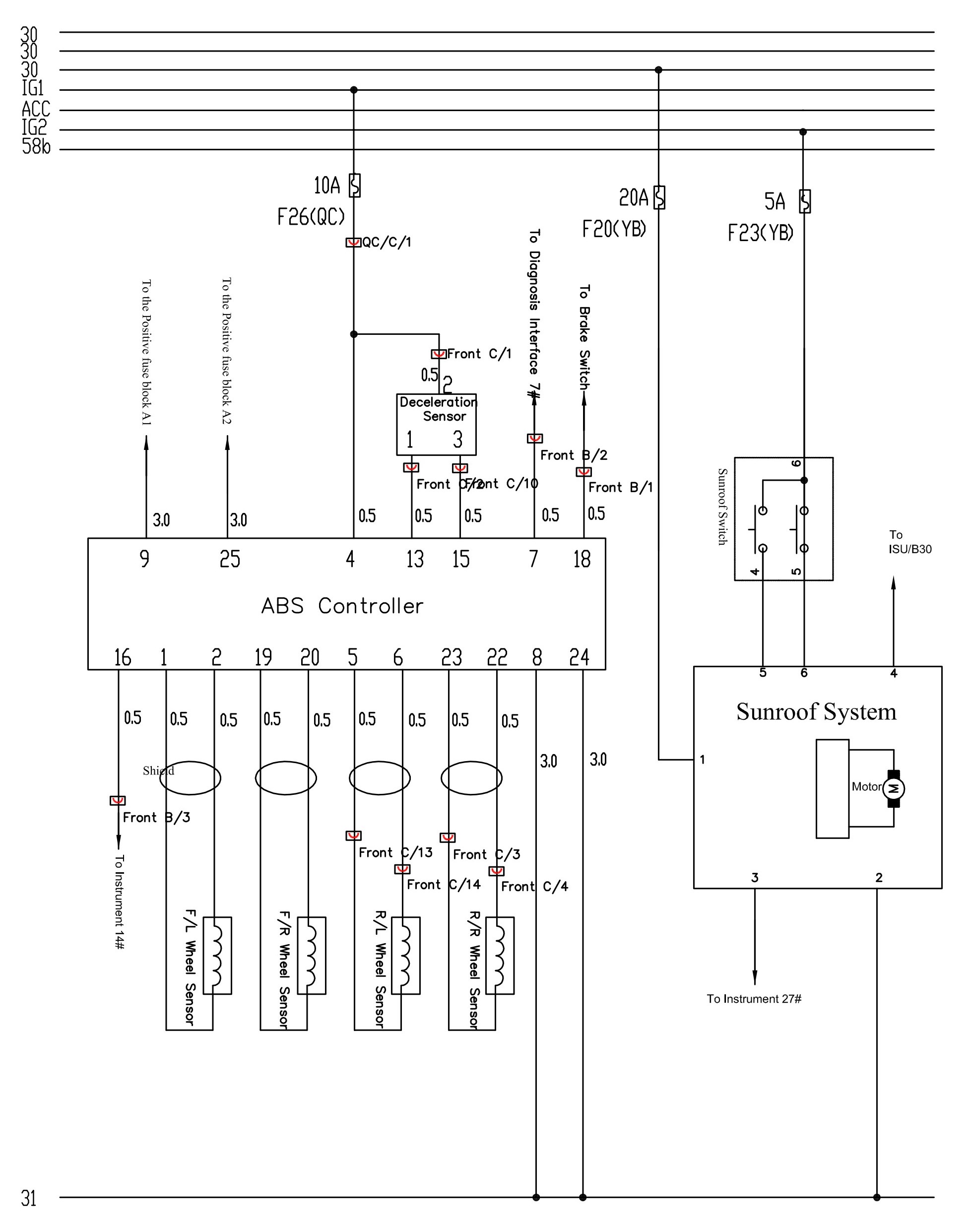
ABS and Sunroof System.
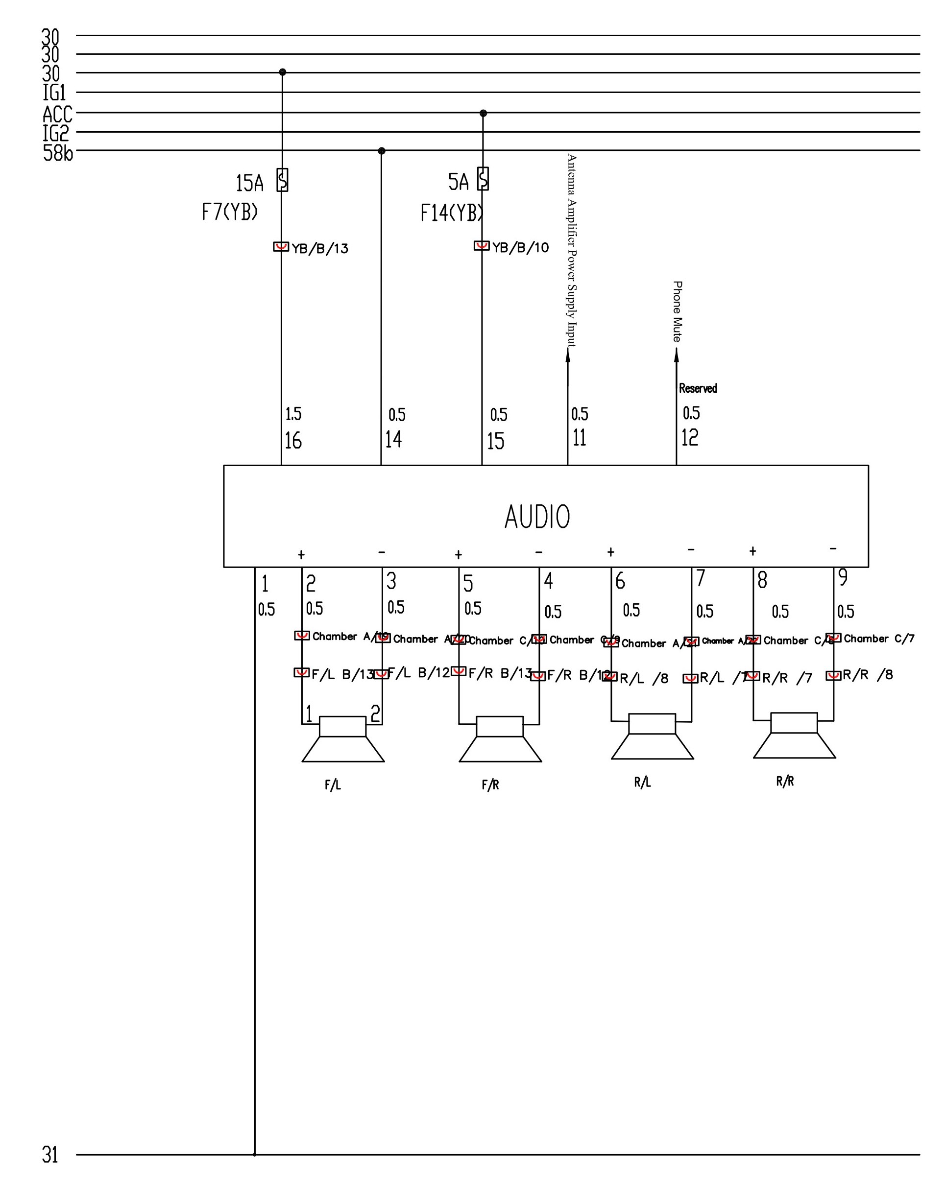
Audio System.
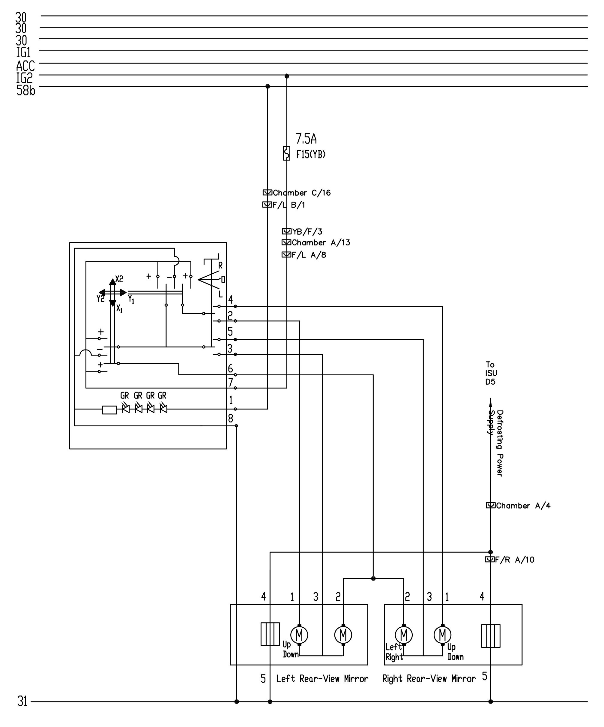
Electric Rear-View Mirror System.
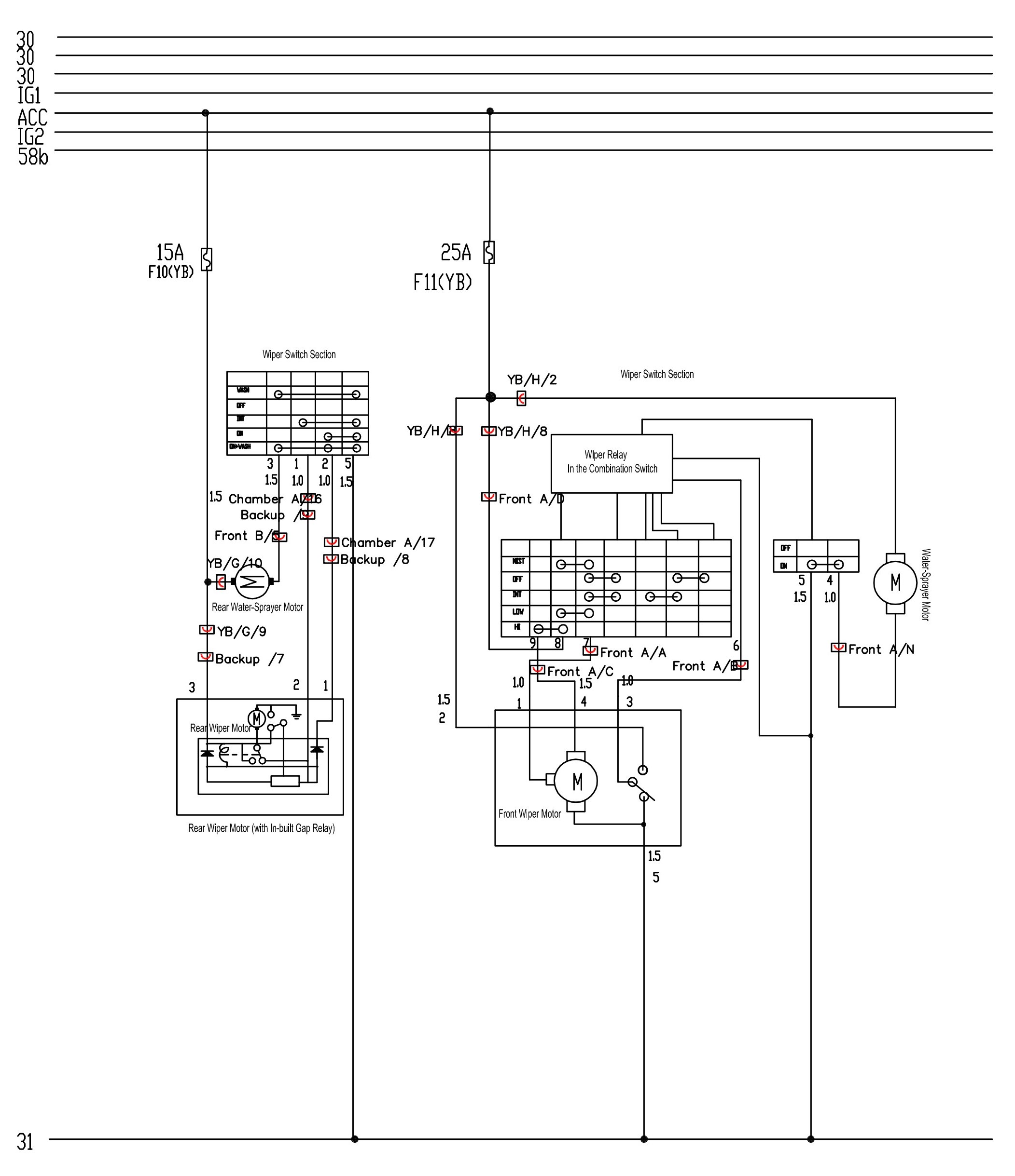
Wiper System.
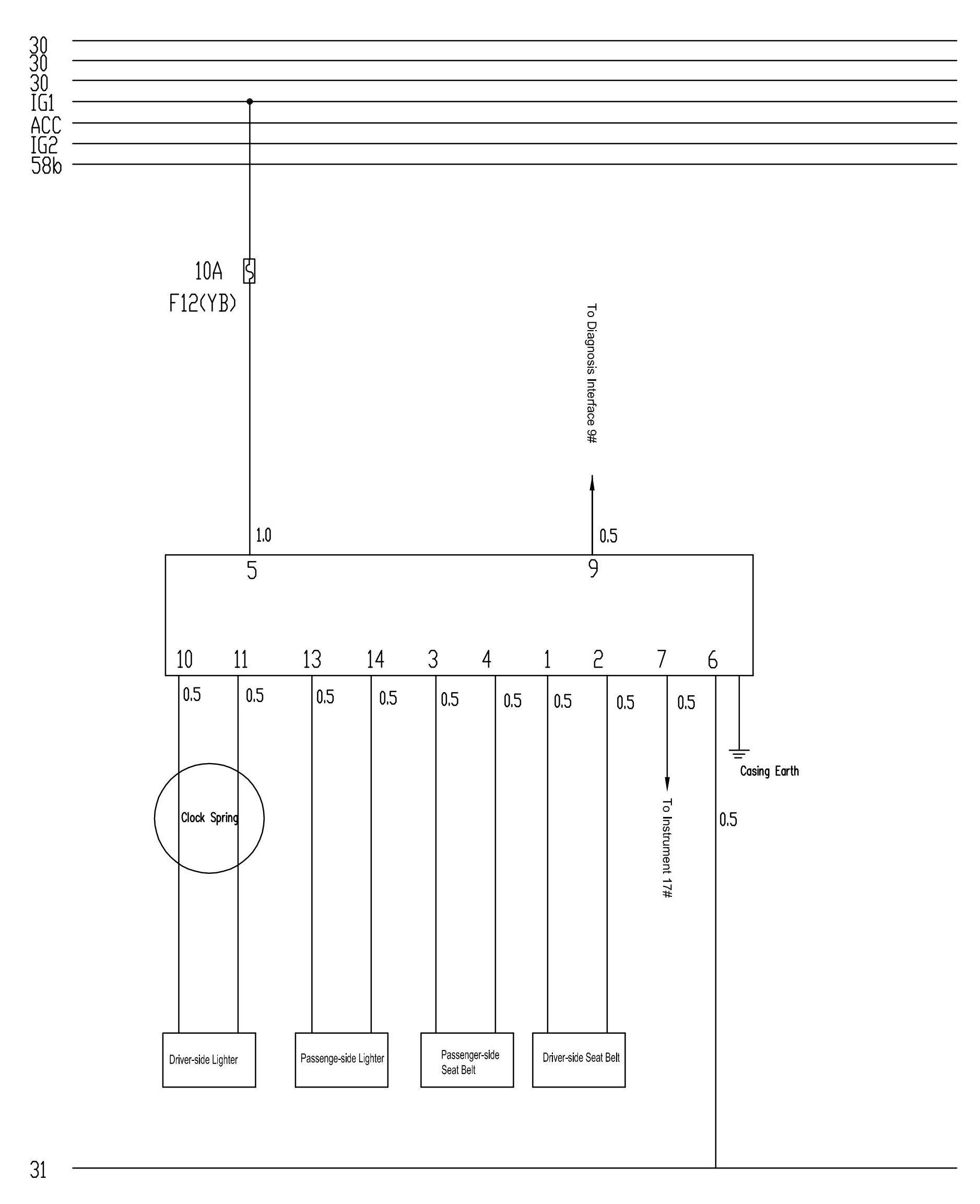
Safety Airbag System.
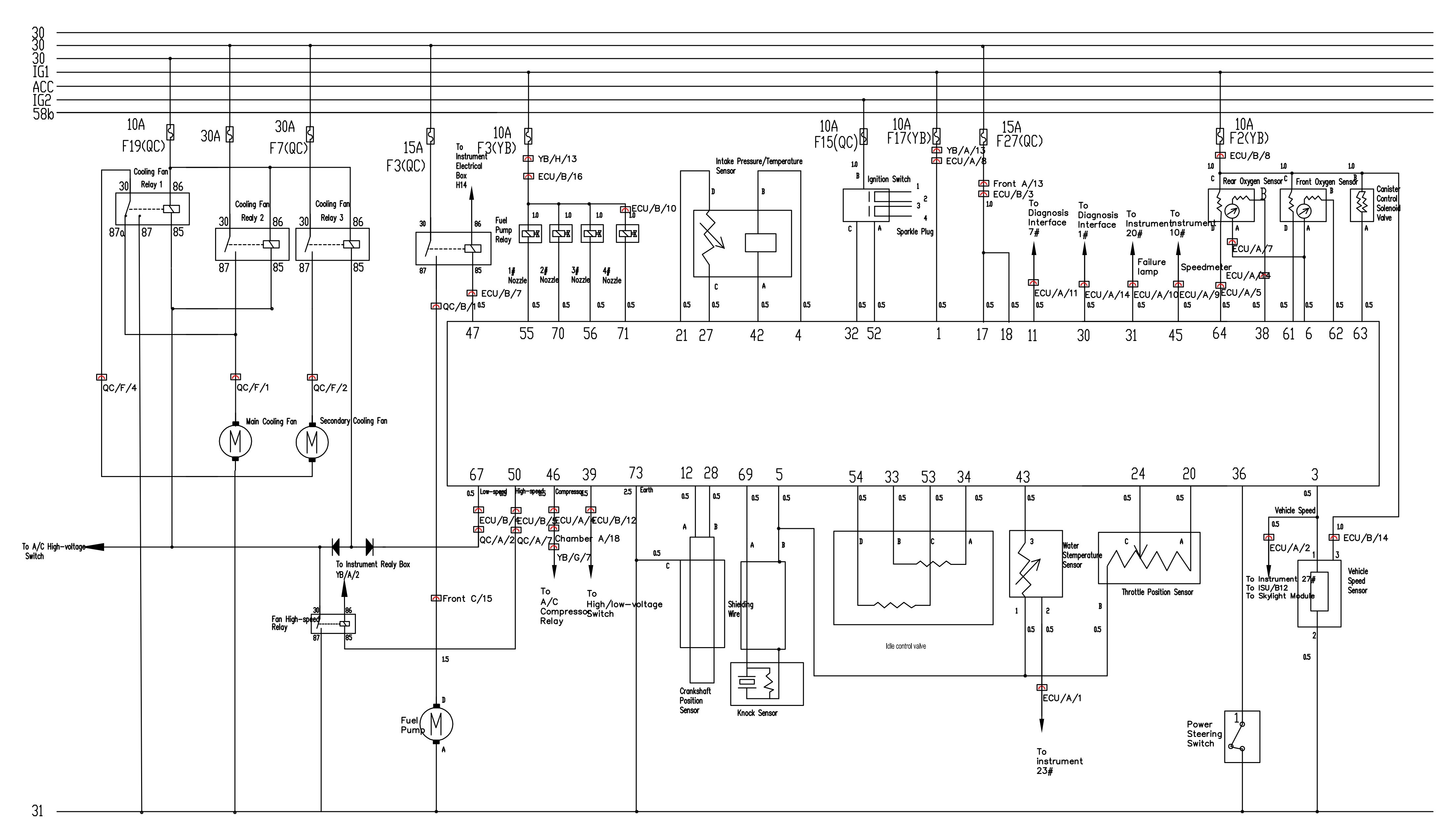
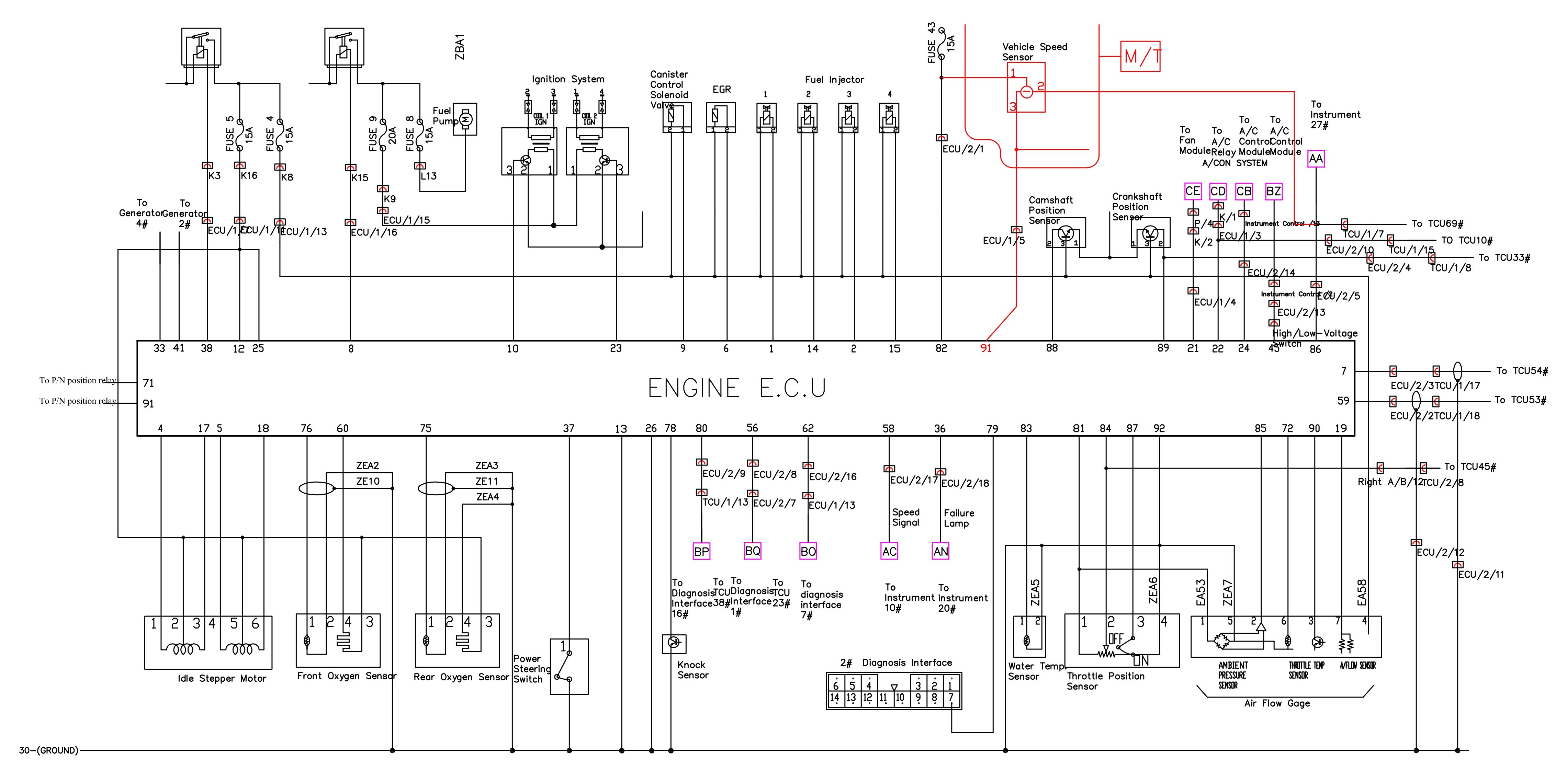
Engine System.
ISU System (Ceiling Lamp Included).
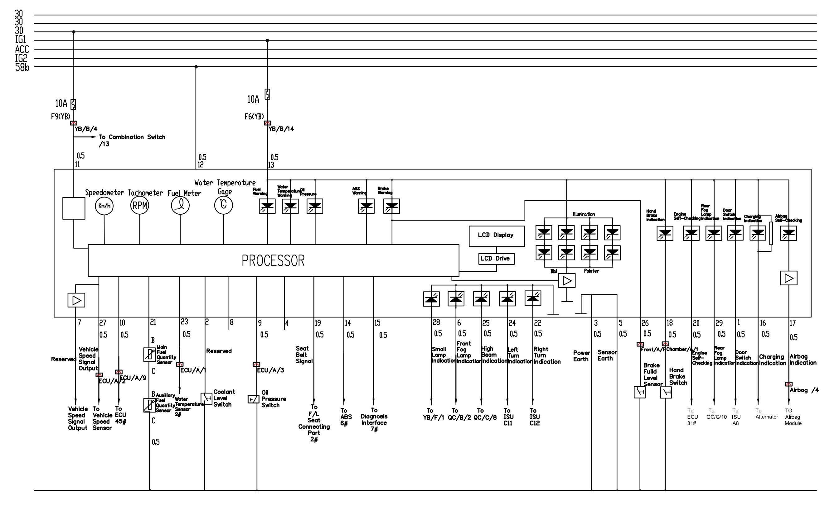
Instrument System.
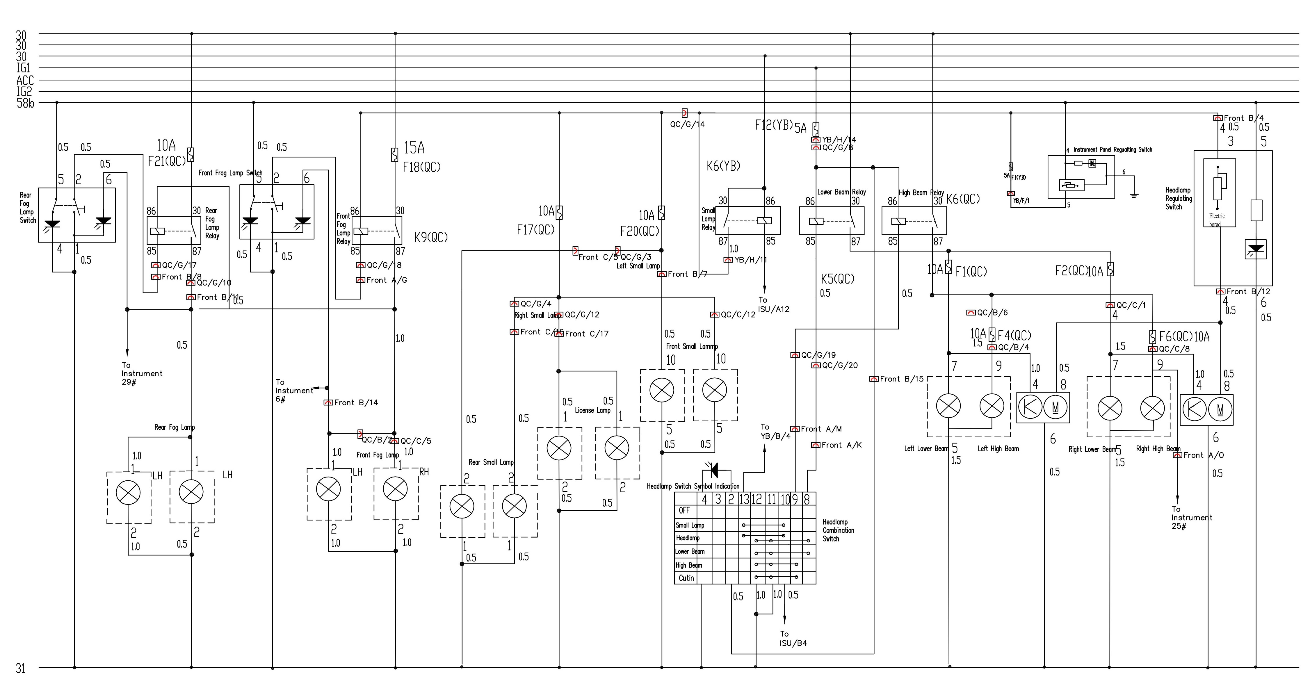
Lighting System.
Brake Signal, Reverse Signal, Cigarette Lighter, Reserved Power Supply, Horn, Seat Heater and Diagnosis Interface System.
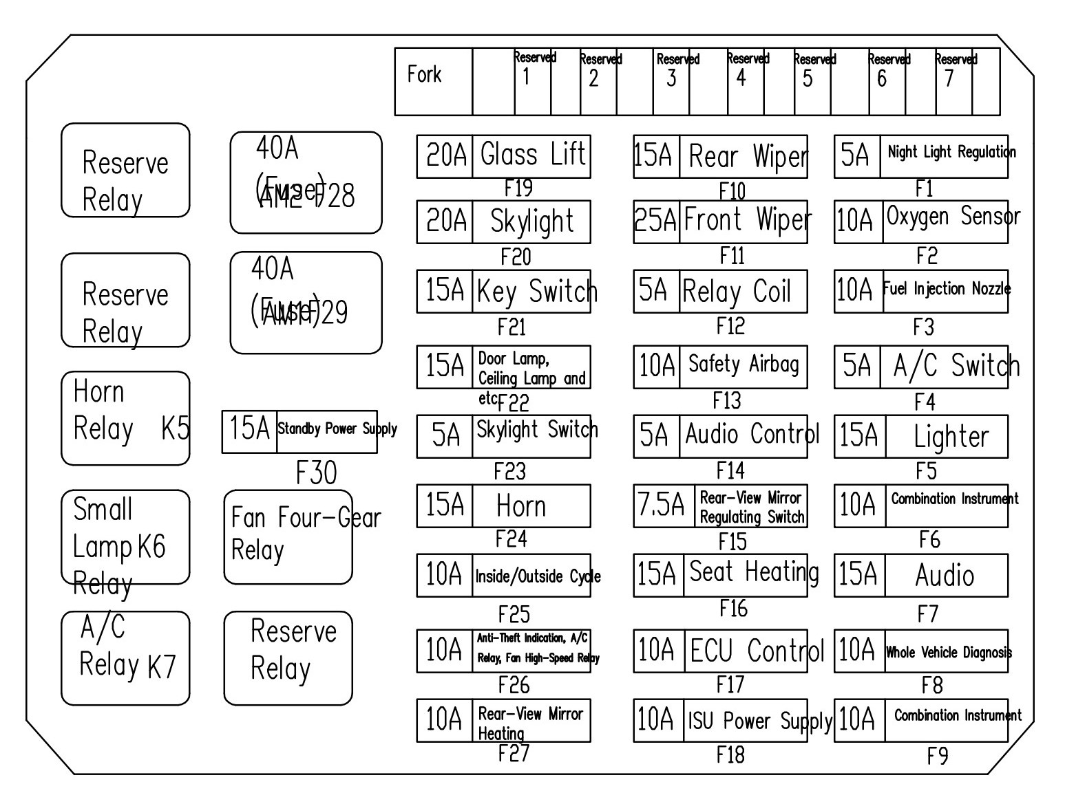
Front Compartment Electrical Box System.
Principle of Front Compartment Electrical Box.
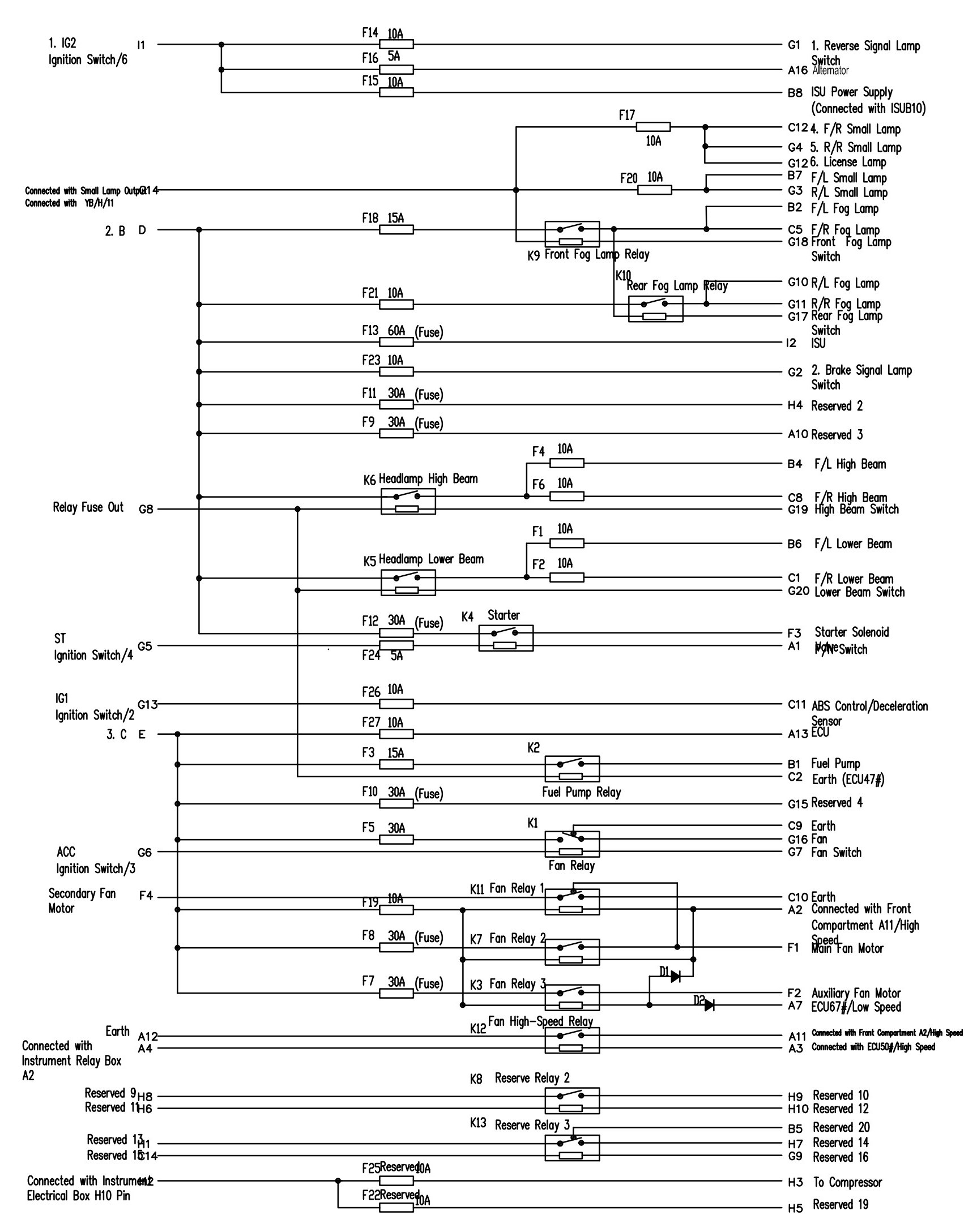
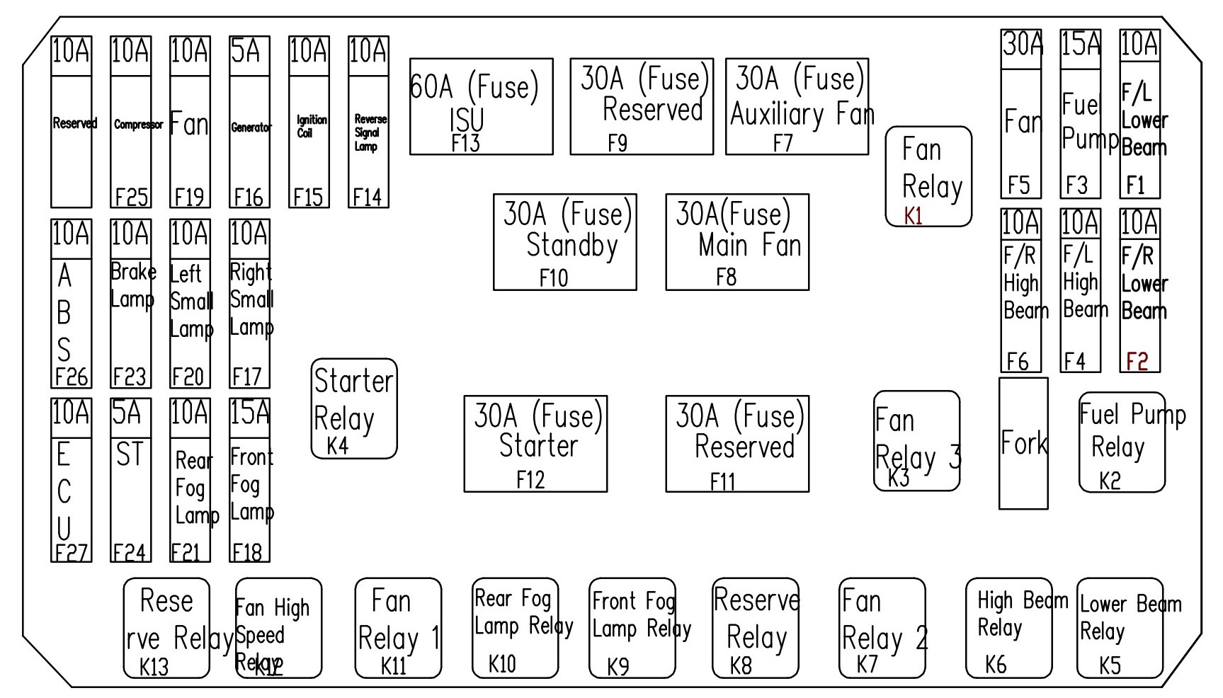
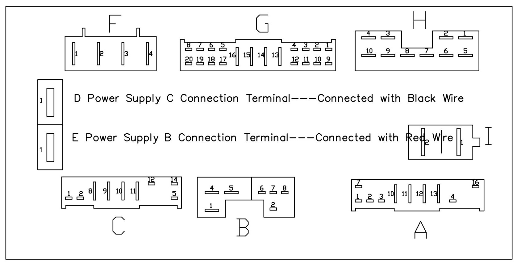
Instrument Electrical Box System.
Principle of Instrument Panel Electrical Box.
Поделиться ссылкой:
Похожие статьи
 Схемы электрооборудования Chery QQ (Chery S11) (English).
 Схемы электрооборудования Great Wall Hover H3/H5 (Hafu, Haval H3/H5, X240).
 Great Wall Body Electric Apparatus (K5-4G63-4G69-2.5TCI Left Hand Drive).
 Great Wall Body Electric Apparatus (K5-4G69-4D20 Right Hand Drive).
 Great Wall Body Electric Apparatus (2010-4G69-2.5TCI-4D20 Left Hand Drive, H3 Shifted to H5 Interior Trim).
 Great Wall Body Electric Apparatus (2010-4D20AT).
 Great Wall Body Electric Apparatus (K5-N2).
 Great Wall Body Electric Apparatus (K5-4D20AT Right Hand Drive).
 Схемы электрооборудования Chery M11.
 Как пользоваться схемами электрооборудования Omoda C5.
 Great Wall Body Electric Apparatus (2011).
 Схемы электрооборудования Chery QQ6 (Cowin 1, Jaggi, S21) (English).
 Схемы электрооборудования Chery M11 (A3, Alve, Chance, Cielo, Cruise, J3, Niche, Orinoco, Ove, Skin, Tengo) (English).
 Great Wall Body Electric Apparatus (K5-4D20 Left Hand Drive).
 Схемы Omoda C5.
